Eng-Tips is the largest engineering community on the Internet

Intelligent Work Forums for Engineering Professionals

Getting 120V from a 240Y/139V XFMR 1

Status
Not open for further replies.

crthompson

Electrical
Aug 8, 2011
75
0
0
US
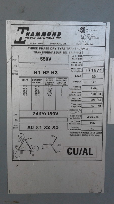
Gentlemen, I have attached a photo of the XFMR in question. The primary of the XFMR is Nominal 550V Delta. Our plant voltage is roughly 580V on all 3 phases. The secondary of the XFMR is 240Y/139V. We are only using two legs of the Y on the secondary. All secondary loads are from phase to neutral (139V). All of our loads are rated at 120V. I am hesitant to put 139V on 120V devices. My question is this... If I were to disconnect the neutral point of the unused secondary winding, wouldn't the voltage from the other two legs to neutral be 120V? At that point, you would have 240V across the two used legs, with the neutral acting as a center tap making it 120V from each leg to neutral. Of course I could be missing something... Any advice would be appreciated!

240Y-139V_XFMR_smwuhk.jpg
 
Replies continue below

Recommended for you

The short answer is NO.
Each secondary winding is producing 139 Volts, regardless of being connected to any other windings.
Try a 120/240:120/240 Volt isolation transformer to generate 120 Volts.
The transformer must have sufficient capacity to carry the maximum possible unbalanced neutral current. No fudging, the maximum current if only the loads on one line are energized.
You may be able to parallel the primary and secondary windings if they are identical.
This will double the capacity. Check for circulating currents before running the windings in parallel.

Bill
--------------------
"Why not the best?"
Jimmy Carter
 
That makes perfect sense Bill. So, would that mean that I would have roughly 278V across the two legs if I connected it in the configuration I mentioned? I'm not going to do this, I just want to make sure I follow...

 
No the two voltages will still be at different phase angles. They must be added vectorily. 139 Volts plus 139 Volts with a 120 degree phase displacement equals 240 Volts.
Look at your secondary diagram:
The secondary diagram is a vector representation of the secondary voltages. You can scale that sketch to any voltage that you wish and the angles and relationships remain the same. There will always be a root 3 (1.73) relationship between the line to line voltages and the line to neutral voltages, be it 120:208 Volts or 139:240 Volts.

Bill
--------------------
"Why not the best?"
Jimmy Carter
 
Understood. I get the vector addition. What I'm having a hard time understanding is why the center point of your vector diagram wouldn't shift when you removed one of the phases. I imagine in my head,(dangerous in there) three rubber bands being pulled by equal magnitudes(139V) in equidistant directions(120 degrees apart). If one of those rubber bands is cut, the angle between the other two would be 180 degrees and the magnitude between the two would be 278V would it not? I can imagine that if the center point is grounded that it might act as an anchor point, keeping the vector diagram from shifting if one leg is removed. Outside of that, I can't seem to understand why the vector diagram wouldn't shift when one leg was lost.

 
You could use three single-phase buck autotransformers connected in wye to reduce the phase voltages to closer to 120 V[sub]LN[/sub], and that might be cheaper than an isolation transformer since the kVA rating of the three units can be lower. Try the Buck and Boost Transformer Calculator from Schneider Electric to see how that might work. Note, I am unaffiliated with Schneider Electric; they just have a convenient tool.

xnuke
"Live and act within the limit of your knowledge and keep expanding it to the limit of your life." Ayn Rand, Atlas Shrugged.
Please see FAQ731-376 for tips on how to make the best use of Eng-Tips.
 
The center point is grounded and acting as an anchor point, so the angle remains 120 degrees from each phase to the grounded neutral.

xnuke
"Live and act within the limit of your knowledge and keep expanding it to the limit of your life." Ayn Rand, Atlas Shrugged.
Please see FAQ731-376 for tips on how to make the best use of Eng-Tips.
 
The first mistake is equating transformer phase angle relationships with rubber bands.
It is what it is.
Nowhere in the description of the phase angle relationships between phases is the ground mentioned or needed.
If you remove the ground connection you will still have the same phase angles, the same line to line voltages and the same line to wye-point neutral voltages.
You will have added an NEC code violation.

Bill
--------------------
"Why not the best?"
Jimmy Carter
 
It is the delta-connected primary winding that is keeping the wye-connected secondary windings at their proper phase relationship, whether the neutral is grounded or not or whether the secondary load is balanced or not.

If the transformer is some distance away from its loads, the voltage drop along the feeder lines will probably bring the utilization voltage closer to 120 volts.
 
Actually there are two connections used to reduce voltage.
Splitting hairs there is the buck connection and the auto-transformer connection.
To use the buck connection, you need a transformer rated 140:20 Volts.
To use the auto-transformer connection you need a transformer rated 120:24 Volts.
That will give you about 123.5 Volts.
If you go up one tap on the primary you will get a nominal 121 Volts.

Bill
--------------------
"Why not the best?"
Jimmy Carter
 
mvcjr gave the answer as to why it wouldn't work. The delta connection on the primary causes the phase angles between the secondary coils.

Look-up the open delta transformer configuration as an example of why disconnecting a single coil doesn't change anything. It still passes 3-phase voltages even with one "leg" missing.

Your rubber band analogy would have worked if you were also modifying the primary of the transformer. If it was a Y-Y connected transformer and you disconnected the primary as you suggested, then the 2 corresponding secondary phases would have shifted to become the voltages you wanted.

If you could break apart the primary delta connection and put the primary coils between the same 2-phases then the secondaries would be in phase and could add directly. But, it'd still be 139V/278V so it wouldn't accomplish what you want.
 
A note on Buck connections and auto-transformer connections:
Even though you may be using the auto-transformer connection, the transformer must still be "buck-boost" rated.
The buck-boost rating has to do with the insulation value of the secondary winding, regardless of the connection.
Regardless of the connection, auto-transformer or buck, the secondary will still see 139 Volts to ground and must have suitable insulation.


Bill
--------------------
"Why not the best?"
Jimmy Carter
 
Don't forget that if in fact the plant voltage is 580V phase-to-phase, you will actually have 253/146V on the secondary with the nameplate ratio nominal tap. Using the 578V tap, you will be close to the nameplate 240/139V.
 
If all of your loads are 120V, just don't use that transformer. Go get one that provides a 208Y120V output.


" We are all here on earth to help others; what on earth the others are here for I don't know.
" -- W. H. Auden
 
Status
Not open for further replies.
Back
Top