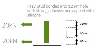
I have a bolt going through 3 composite layers loaded in double shear. I need to know the GFRP tear out strength and bearing strength to verify the integrity. Does anyone have any advice/applicable standards to calculate bearing strength and/or tear out strength? How does this usually relate to tensile strength etc.? higher, lower?
Navigation
Install the app
How to install the app on iOS
Follow along with the video below to see how to install our site as a web app on your home screen.
Note: This feature may not be available in some browsers.
More options
Style variation
-
Congratulations MintJulep on being selected by the Eng-Tips community for having the most helpful posts in the forums last week. Way to Go!
You are using an out of date browser. It may not display this or other websites correctly.
You should upgrade or use an alternative browser.
You should upgrade or use an alternative browser.
GFRP Composite Tear Out and Bearing Strength?
- Thread starter JD_WTG
- Start date
- Status
- Not open for further replies.
SWComposites
Aerospace
Short answer: you can’t calculate those strengths; need specific joint test data.
Neither is related to tensile strength. Tear out is a shear failure mode. Bearing is sort of a complicated compression failure mode.
Design with large edge margin (e/D = 3+) and you are unlikely to fail in tear out before bearing.
Bearing strength in double shear is usually greater than laminate compression strength.
- Thread starter
- #3
If it's a single pin joint with composite lugs, strongly recommend test validation. Consider that in metallic pin hoints, sizing methods are usually empirical (eg melcon, cozzone, hoblit) given the complexity of stress state and failure modes. You're adding to this the complexity of composite mayerial failure modes.
Also watch your pin diameter selection, might be a little more susceptible to pin bending failure than a metallic joint, that said being gfrp the laminate is by far likely to be critical.
In metals Ftu can be a conservative preliminary estimate of Fbru, however I wouldnt advise that as a general approach for composites.
- Thread starter
- #5
Hi Ng2020. If i understand you correctly - your opinion is that the composite being GFRP, its likely to be quite strong compared to the pin? The pin goes through very thick sections of composite. Two outers being 60mm and the inner bein 80mm.
Apologies for my ignorance - composites are a new area for me in terms of structural engineering.
Apologies for my ignorance - composites are a new area for me in terms of structural engineering.
Actually I was initially assuming that your laminates would be quite thin and probably less capable than the pin. However those are quite substantial. Make sure you do a pin bending check to ensure you choose the right pin size and material. Keep it simple and choose a conservative moment arm: the laminate will be quite soft so you would be best to conservatively assume a uniform load diatribution through the thickness of the laminate.
I think there's a reasonable example (though nore complex) for a metallic pin joint in the USAF stress manual (google it)
I think there's a reasonable example (though nore complex) for a metallic pin joint in the USAF stress manual (google it)
- Thread starter
- #8

Please note the 3 layers/plates are all different sections of GFRP in which the outer and inner layer are connected to one component and the middle layer is connected to another so the bonding between sections is prone to debonding when the outer and inners are pulled relative to the centre layer.
SWComposites
Aerospace
That pin looks way too skinny for those thicknesses.
- Status
- Not open for further replies.
Similar threads
- Replies
- 1
- Views
- 854
- Locked
- Question
- Replies
- 0
- Views
- 667
- Replies
- 2
- Views
- 711
- Replies
- 14
- Views
- 2K
- Locked
- Question
- Replies
- 5
- Views
- 586
