Continue to Site

Eng-Tips is the largest engineering community on the Internet

Intelligent Work Forums for Engineering Professionals

  • Congratulations KootK on being selected by the Eng-Tips community for having the most helpful posts in the forums last week. Way to Go!

Girder Analysis Varying in Cross Section Made of Pin-Connected Elements

Status
Not open for further replies.

ETX

Structural
Aug 8, 2019
12
Would like a quick sanity check on my analysis approach for a long span girder made up of shorter pin-connected elements. I won't go into the details, but instead of using a single, prismatic girder, a smaller sized girder and a larger sized girder are pin connected to each other using essentially a built-up bracket. See the attached sketch. Basically, the three pieces are pin connected to each other in the field to form a single girder. The sketch is subpar, but basically the center of the pin-eye of the connecting plates is in line with the member flanges, so the adjoining members can be pin-connected and provide continuity. My thoughts on this structure are below:

1) The girder is simply supported, so since there are no redundant load paths, each support must receive half the load. Even though the thicker girder is stiffer, it will receive the same share of load as the thinner one since the girder is simply supported. The stresses just won't be as high.

2) Analyzing the girder as a nonprismatic member and thereby calculating the deflections and stiffness factors for each member and then appling moment distribution isn't necessary since the girder is simply supported. Same rationale as point 1.

3) The top and bottom pins resolve the bending moment from the girder through a couple, causing tension on either the top/bottom set of connecting plates and compression on the opposite plates. The strength of the pin-connected elements can then be calculated using section D5 of the AISC Manual for Pin-Connected members.

4) If a moment capacity was to be specified for the connection elements, then the moment capacity would be the allowable tension on the pin-connected element as calculated using the AISC formulae multiplied by the lever arm (distance between the top and bottom pins).

5) Are the stresses magnified at the connecting bracket? The stress at the inner radius should be maximum. Should the forces on the bracket be resolved about each connecting point to verify the member strength?

Am I missing anything? This seems simple enough but I have never seen any girders connected in this fashion and want to make sure all my bases are covered.
Thank you all.
 
 https://files.engineering.com/getfile.aspx?folder=6793bb0c-4837-4df4-a6a2-a1042d585327&file=Sketch.pdf
Replies continue below

Recommended for you

ETX said:
2) Analyzing the girder as a nonprismatic member and thereby calculating the deflections and stiffness factors for each member and then appling moment distribution isn't necessary since the girder is simply supported. Same rationale as point 1.
For shear and moment I agree but your going to need to do the non-prismatic analysis for deflections, being simply supported it works nice for conjugate beam since the support conditions remain the same.

ETX said:
3) The top and bottom pins resolve the bending moment from the girder through a couple, causing tension on either the top/bottom set of connecting plates and compression on the opposite plates. The strength of the pin-connected elements can then be calculated using section D5 of the AISC Manual for Pin-Connected members.
As sketched I think this is hard to justify, your pumping the moment couples into the webs and hoping they get back out into the flanges and haven't really addressed shear transfer at all.


Open Source Structural Applications:
 
The sketch doesn't quite make sense. In the elevations, there are an upper and lower eye for the pins, extending from what appears to be a single flange.
But in the plan view you have three "fingers" for eyes, as though they are welded to the flanges. Which is it?

Some other comments:
1. You will have very high concentrated hot-spot stresses where the eyes attach to a web (or flange). Rupture checks are required.
2. If three eyes top and bottom, then there could be variation in how much load goes into each eye as their relative stiffnesses might be a bit different (haven't thought this through yet but I think it is correct).
3. The three sections will not behave as a single beam with respect to lateral torsional buckling - so the entire shape or, at the very least, the two pinned connection points should be fully braced.
4. Why not use a simple / traditional flange splice detail with flange cover plates and bolts?
5. Agree with Celt83 in that the full potential of the girder flanges aren't being utilized here.


Check out Eng-Tips Forum's Policies here:
faq731-376
 
1) Agree.

2) Agree. You didn't mention calculating deflections, only using non-prismatic elements to work out moment distributions. And I agree, that's not required.

3) Agree. If you can design a pin connection to locally deal with the tension and compression forces, I think that you can take it as a given that those same forces can spread out into the flanges as required.

4) Agree.

5) Yes and yes. The proportions of the connecting bracket will likely invalidate the assumption of Bernoulli flexure entirely. As such, the bracket probably needs to be considered as a "connector" more than a beam beam segment.

OP said:
Am I missing anything?

6) The big one for me would be the lateral torsional buckling that JAE mentioned. Tough to predict the behavior without bracing so I'd push pretty hard to have the bracing.

7) If you need to calculate deflection, that deflection would need to consider both the change in cross section and slip in the bolts at the connections unless those will be slip critical. Kind of like the flexural version of how we calculate deflection in diaphragm chords.

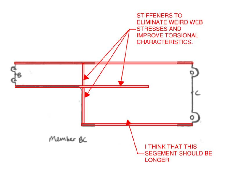
8) I recommend the detailing alterations shown below.

c01_et1mns.jpg


HELP! I'd like your help with a thread that I was forced to move to the business issues section where it will surely be seen by next to nobody that matters to me:
 
Thank you all very much. I agree, deflection will need to be checked also and I will probably use the conjugate beam method like you mentioned Celt83.

JAE, the "fingers" are welded to the top and bottom flange (resembles a built-up girder). All connecting plates with pin-eyes are of the same thickness and material, so there should be equal load distribution. Failed to mention that. If you had a better sketch it would definitely help. I'll recommend bracing to preclude LTB.

Thanks KootK, I wasn't certain whether the bracket could be treated as a beam segment, so I am glad you mentioned that. I also failed to depict in the sketch a full-length web stiffener at the end of the connecting plates on the bracket, which looks very similar to the vertical stiffener of your sketch.

Appreciate the help of the eng-tip forum.
 
I'd think as well any slop/tolerances in the pins needs to be added into the deflection. So tolerances will be critical to getting a handle on this. I'd think as well you'd want the pins to be concentric, two shear planes.

I personally wouldn't use this arrangement on the basis of the information supplied, but if it must be used then the capacity of the girder would be kneecapped by the presumably lower strength relating to loads in the web. Also agree with all the other suggestions and limitations others have noted.

What's the real situation forcing you down this path out of interest? Maybe there's another much better solution that you're potentially missing?
 
Given that your brackets will be attached the flanges rather than the webs, you may have to consider local bending in the flanges to deal with the associated eccentricity. You might also need too rethink your shear connection and make that a thing separate from the flange brackets/pins. Maybe just a couple of shear splice plates with bolts. Otherwise, carrying the beam shear through the flanges could be a problem.

The right combination of stiffeners might alleviate these things but you'd have to show us what you've got in mind before we could comment intelligently.

HELP! I'd like your help with a thread that I was forced to move to the business issues section where it will surely be seen by next to nobody that matters to me:
 
Agent666, here is the situation. I work at a chemical plant and we have a lift coming up where we have reached out to a vendor for assistance. They are putting up what can be best described as a portable gantry crane. For shipping requirements, they are not using a single girder member, but are going to pin the girder together in the field using the parts shown in the sketch. I'd love to show the drawings but for proprietary reasons I am not. I have been asked to review the lift rig so I wanted to reach out and seek others' opinions as this type of connection/splice is not typical and I have never ran across anything other than web/flange splices in my time.

Not too concerned about deflection because of the lack of serviceability requirements.
 
I think then you are saying this thing is floating in space without any restraints (unsure how it fits into larger system). Possibly also carrying compression? So the concerns raised by others regarding restraining the pinned locations out of plane is definitely required. Keep in mind what is proposed is a pin about the minor axis but not so much of a pin about the major axis as can carry some moment, so bad news if no restraint and compressive loading or if subject to lateral torsional buckling.

If you didn't want a traditional bolted splice to the flanges and web, what about a channel either side of the web of sufficient length to resolve the bending loads into vertical couples on a group of bolts?
 
Status
Not open for further replies.

Part and Inventory Search

Sponsor