ETX
Structural
- Aug 8, 2019
- 12
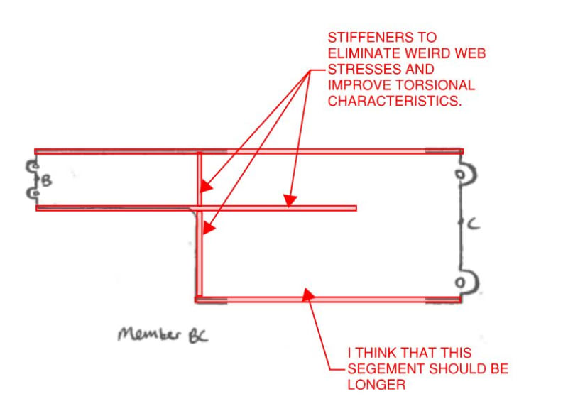
Would like a quick sanity check on my analysis approach for a long span girder made up of shorter pin-connected elements. I won't go into the details, but instead of using a single, prismatic girder, a smaller sized girder and a larger sized girder are pin connected to each other using essentially a built-up bracket. See the attached sketch. Basically, the three pieces are pin connected to each other in the field to form a single girder. The sketch is subpar, but basically the center of the pin-eye of the connecting plates is in line with the member flanges, so the adjoining members can be pin-connected and provide continuity. My thoughts on this structure are below:
1) The girder is simply supported, so since there are no redundant load paths, each support must receive half the load. Even though the thicker girder is stiffer, it will receive the same share of load as the thinner one since the girder is simply supported. The stresses just won't be as high.
2) Analyzing the girder as a nonprismatic member and thereby calculating the deflections and stiffness factors for each member and then appling moment distribution isn't necessary since the girder is simply supported. Same rationale as point 1.
3) The top and bottom pins resolve the bending moment from the girder through a couple, causing tension on either the top/bottom set of connecting plates and compression on the opposite plates. The strength of the pin-connected elements can then be calculated using section D5 of the AISC Manual for Pin-Connected members.
4) If a moment capacity was to be specified for the connection elements, then the moment capacity would be the allowable tension on the pin-connected element as calculated using the AISC formulae multiplied by the lever arm (distance between the top and bottom pins).
5) Are the stresses magnified at the connecting bracket? The stress at the inner radius should be maximum. Should the forces on the bracket be resolved about each connecting point to verify the member strength?
Am I missing anything? This seems simple enough but I have never seen any girders connected in this fashion and want to make sure all my bases are covered.
Thank you all.

