Continue to Site

Eng-Tips is the largest engineering community on the Internet

Intelligent Work Forums for Engineering Professionals

  • Congratulations waross on being selected by the Eng-Tips community for having the most helpful posts in the forums last week. Way to Go!

Girder Anchorage Hook forces 10

Status
Not open for further replies.

Quence

Structural
Jul 16, 2018
84
Please see attached image. In airports and open hallways and malls.. you can often see long big secondary beam ends framing into girders. I'm concerned about the details of the anchorage and hooks. This is not often mentioned in structural books. Do you make the hook detail at the edge of the girder? I'd like to know the behavior of the vertical part of the hook.. would the forces be to the left or right? Won't it spall the concrete cover to the left?
 
 https://files.engineering.com/getfile.aspx?folder=8a6e71cd-6e5a-4fc9-818c-fde2b7097ea5&file=anchorage_hook.jpg
Replies continue below

Recommended for you

OP said:
Nowhere is it mentioned about the secondary beam being pinned. So when the torsional cracking occurs in the edge girder.. where would it redistribute the forces? In the edge girder itself? How? If the secondary beam is not pinned (and it doesn't assume it's pinned).. it won't get redistributed there because the default assumption is its moment connected.

The forces get distributed in other members than the edge girder.

Imagine the torsional cracking as a torsional "pin". If the edge beam twists itself apart (but somehow still supports the vertical loads of the supported beams) does the structure still stand up? The answer should be yes; the loads go to all the other members holding up the structure. This can be easily modeled in ETABS. Put a torsional release in your edge girder; you just redistributed the forces and you still have a moment connection between the edge girder and the supported beams.

OP said:
What can you say about deflection and torsional stiffness?

They're mostly unrelated. A deep steel wide flange beam will not deflect much along it's strong axis (high flexural stiffness) but has low torsional stiffness relative to the flexural stiffness. This is why an unbraced W8 floor beam can be stronger than an equal weight W12 floor beam, the lateral-torsional stability of the W12 is low compared to the more compact W8 beam.

OP said:
When I put lighter edge girder in Etabs.. the deflection is more and torsion is minimum yet there is almost zero moment at the joint (even though the setting is full moment connection).. so it seems deflection governs more than torsion stiffness in the edge girder?

This gets back to the earlier comments; your edge girder's relative stiffness is small compared to the continuous span of the floor beam; making the edge girder even lighter makes this disparity even greater.

Try this; make the interior span of the floor beam small (or delete it altogether). Your torsion to the edge girder should significantly increase and now it's the stiffest path for the load to go.

Ian Riley, PE, SE
Professional Engineer (ME, NH, MA) Structural Engineer (IL)
American Concrete Industries
 
If the torsional cracking in the edge girder occurs.. won't it engage the torsion stirrups increasing it's fy until yield? Without yielding.. there would be no redistribution of forces.

And you assumed the torsion stirrups have yielded? Assuming it does. Let's imagine you are hanging on tree branch with your arms twisting the front branch.. then the torsion exceeds in the branch and it cracks. Won't your hold of it continue until the branch just breaks? How does redistribution here works?

try this; make the interior span of the floor beam small (or delete it altogether). Your torsion to the edge girder should significantly increase and now it's the stiffest path for the load to go

When I removed the secondary beam at Etabs, the slabs are connected to the edge girder by tributary loading and it is just small so the torsion didn't increase. Anyway how do you make torsion release in Etabs?
Appreciated your help so much. Thanks.
 
Quence said:
Nowhere is it mentioned about the secondary beam being pinned. So when the torsional cracking occurs in the edge girder.. where would it redistribute the forces? In the edge girder itself? How? If the secondary beam is not pinned (and it doesn't assume it's pinned).. it won't get redistributed there because the default assumption is its moment connected.

The secondary beam is not pinned. Before torsional cracking, the secondary beam has an end moment equal to 2*Mt where Mt is the torsional moment in the edge girder. After torsional cracking, 2*Mt is suddenly reduced. The reduction is redistributed to the secondary beam, creating an increase in positive and negative moment at the central support (if it exists). If it does not exist, then the positive moment increases by precisely the reduction in 2*Mt if girder cracking occurs simultaneously at both ends of the beam.

BA
 
There is a very good reason why engineers don't rely on torsional moments in indeterminate structures. If the girder suddenly cracks in torsion, the secondary beam has lost its end moments.

When torsional moments are required for stability of the structure, it cannot be ignored. Personally, I don't like to design structures which rely on torsion for stability of the structure.

In the Canadian code, if the torsional moment exceeds 0.25Mcr (cracking moment), even if it just compatibility torsion, then minimal torsional reinforcement must be provided. I believe ACI is the same but I'm not certain.

BA
 
BA. You haven't mentioned the torsion stirrups.. if the girder suddenly cracks in torsion, and there are sufficient torsion stirrups.. would the secondary beam lose its end moments?

Let's review the possible scenerios.

1. If the secondary beam end is designed as pinned with weak top bars... the top bars would yield first before the torsion failure in the edge girder? Or would the edge girder failed first in torsion before the top bars in the secondary beam end yielded?

2. If the secondary beam end is designed with many top bars and significantly moment connected.. after torsion failure in the edge girder.. would the secondary beam lose its end moment or is it still moment connected to the failed edge girder.. what would occur then in this case? How would the redistribution occur?
 
Quence, you still don't seem to be able to see the distinction between conservatively designing the secondary beam ignoring the (small) moment restraint provided by the edge beam, and actually providing a pinned connection. It's a typical simplification in such cases to provide a monolithic connection, but ignore the reduction in positive moment in the secondary beam.
 
Quence said:
BA. You haven't mentioned the torsion stirrups.. if the girder suddenly cracks in torsion, and there are sufficient torsion stirrups.. would the secondary beam lose its end moments?

Read your own post which says in part:
At torsional cracking, however, a large twist occurs under an essentially constant torsional moment, resulting in a large redistribution of forces in the structure (Collins and Lampert 1973; Hsu and Burton 1974).

Quence said:
1. If the secondary beam end is designed as pinned with weak top bars... the top bars would yield first before the torsion failure in the edge girder? Or would the edge girder failed first in torsion before the top bars in the secondary beam end yielded?

If the secondary beam is designed as pinned, it makes no difference which fails first. The point is, you cannot rely on the torsional moment at the end of the secondary beam.

2. If the secondary beam end is designed with many top bars and significantly moment connected.. after torsion failure in the edge girder.. would the secondary beam lose its end moment or is it still moment connected to the failed edge girder.. what would occur then in this case? How would the redistribution occur?

After torsional cracking, the midpoint of the girder rotates. The beam is still moment connected to the midpoint of the girder, but they both rotate which means the end moment of the beam is reduced. The redistribution would occur by applying a corrective moment to each end of the secondary beam.

BA
 
Quence: If you're struggling with these concepts you're going to really have trouble with P-delta second order effects, prestressing, and high-seismic design.

At this point I feel like we're kind of going around in circles. Not saying anything by it but it probably would be good to take these questions to someone who can discuss these is person. Drawing a few diagrams or otherwise visually explaining these concepts might help you out more than what we can do over a forum.

Either way, keep at it. Eventually things will start clicking into place.

Ian Riley, PE, SE
Professional Engineer (ME, NH, MA) Structural Engineer (IL)
American Concrete Industries
 
After reading it over and over again. I understood it already.

For normal residental and not so large span loadings. The difference in positive midspan moments between forced pinned secondary beam and full moment connection is not so large.. so even if you don't make it pinned.. the positive moment is accounted for.

It is only in heavy loadings and long secondary beams that there is big difference.. this is when the torsion stiffness of the edge girder is being engaged at overdrive.. here a pinned secondary beam design would be safer due to possible torsion cracks occuring suddenly in the edge girder.. this is because the torsion stiffness is weak there.
I got the general idea. Many thanks for all of you (BA, TEH, Rodrods, Hokie).

Unfortunately. My mentor team ignore all of this as his computer operators only rely on Etabs output of their 50 storey building and they are designing many buildings simultaneously. My mentor is president of the company and dont spend all time analyzing each design.. the operators don't understand the pinned arguments you guys were explaining or concepts about moment redistribution. The operators said their job is only to find the steel reinforcement in etabs and it is up to the contractor to implement the design. But in another company. I saw the structural drawings as having only 2 top bars in the secondary beam framing into the edge girder.. while in my mentor's company.. it's heavily loaded. So I guess i'll change mentor soon.
 
To an extent, we can be your mentors. I'm happy to do whatever I can to further your development. It's always better to have a flesh and blood, in person mentor but my experiences here have taught me that there are parts of the world where that simply isn't a realistic option for many folks.

I'm hesitant to reopen such a lengthy thread but I see that I was personally summoned in several spots on this one to speak to shear friction issues. And I don't like to leave a man behind on the field of battle as it were. A brief summary of the pertinent issues.

1) I believe that there is indeed such a thing as a purely vertical shear failure through monolithic concrete. It has a name and that name is direct shear. It also has a published value in the US of about 10 x SQRT(f'c). It makes an appearance in CRSI's guide on pile cap design as well as a few other places. It's a rare thing and, as referenced by TME above, I believe that the only proof supplied to demonstrate it's rarity was supplied by me, previously, here at Eng-Tips.

2) We're generally encouraged to use tension side reinforcing for shear friction because, in the typical case with moments present, the force in the tension side reinforcing is counterbalanced by compression on the compression side. And it's that compression side clamping that really makes shear friction a viable thing. Anyone would be forgiven for misunderstanding this for several reasons. Firstly, we ignore this all the time in common practice. Designers will shear friction connect shear walls above and below slabs assuming that all of the bars contribute equally. Secondly, to my knowledge, the very testing upon which shear friction relies was done in such a way as to preclude the presence of moments altogether. I consider that a bit unfortunate given that most real world situations involve moment.

3) I do personally believe that compression block rebar reduces the effectiveness of shear friction. I think that this is partially born out in the provisions that only allow inclined bars to be used in shear friction applications when the bars would naturally be in tension. Compression bars are a no go. In my mind, any compression bar reduces the compression in the concrete and therefore reduces the all important shear friction clamping force. Some shear may well end up in the compression bars as, essentially, dowel force. But that's a whole different animal replete with app D style breakout concerns etc.

4) I think that OP is fundamentally on to something with his concern for direct shear in these joints. Consider that we take it for granted that a common flexural crack still remains an essentially monolithic direct shear joint. Clearly, there must be some limit on the width of flexural crack that is acceptable before shear across it becomes a concern? And, if we're not "designing" the top bars for any meaningful criteria, how can we know that crack width is appropriately limited?

5) I fully acknowledge that shear failures of this sort do not appear to have caused problems in the past. That said, in the past, most of us were putting meaningful top steel in these joints. I'm not feeling so good about a future where the profession is dominated by know nothing "operators".

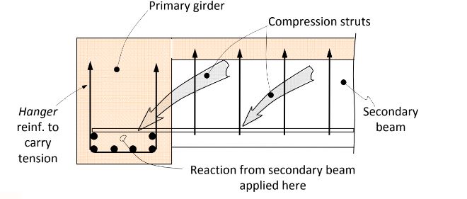
6) If your connection is suitably detailed and you're willing to tolerate large cracks in the top of the supported beam, I believe that you can theoretically get by with no top steel at all following the hanger steel strut and tie model suggested by the sketch below. I don't love it for the reasons discussed above however. Additionally, and fundamentally, a good STM model should reflect expected elastic stress distributions. In the absence of meaningful top steel, I would submit that the hanger STM fails that litmus test.

CO1_opkuzb.jpg


I like to debate structural engineering theory -- a lot. If I challenge you on something, know that I'm doing so because I respect your opinion enough to either change it or adopt it.
 
Status
Not open for further replies.

Part and Inventory Search

Sponsor