Continue to Site

Eng-Tips is the largest engineering community on the Internet

Intelligent Work Forums for Engineering Professionals

  • Congratulations KootK on being selected by the Eng-Tips community for having the most helpful posts in the forums last week. Way to Go!

Girder System Load Distribution 3

Status
Not open for further replies.

GODs HAT

Structural
Apr 3, 2024
4
I'm designing a transfer girder which has a tight deflection criteria and the depth of girder is restricted by some ARCH constrains. I'm wandering into a idea of using 3 identical parallel girders( transfer column sits on middle girder)to distribute the column loads and use the stiffness of all three girders combined. I'm thinking of using tie bracing to distribute the load along three girders and engage the stiffness of all three girders. My question is that if my assumption is valid that the total downward load from transfer column will be resisted by the stiffness of all three girders combined as long my bracing is good in strength to transfer the load to the outer girders? If not, what stiffness is available for the deflection at the middle girder?
 
 https://files.engineering.com/getfile.aspx?folder=dd40aa3b-711f-4562-be5c-b8cd639a1366&file=Girder_System.pdf
Replies continue below

Recommended for you

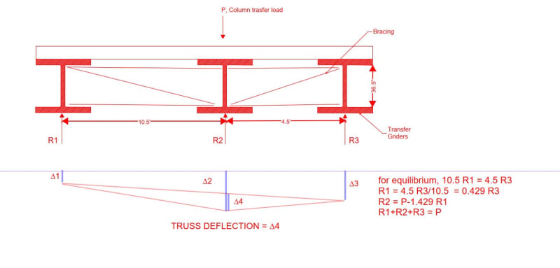
It could be a bit of work, but it is calculable. see below

Capture_wg8lwx.jpg
 
Another way that may result in less total deflection would be to use 3 girders that are not identical. The moment of inertia of each girder is proportioned so that deflection, borrowing BA's terms, Δ1 = Δ2 + Δ4 = Δ3

 
I think I'd rather a clearer load path... Would you not be better off not having a central girder and using a transverse beam(s) to transfer load to the outer beams? (Obviously that's potentially 1/3 less capacity so the outer beams would need to be bigger/heavier etc. )
 
We would be better off by building up the central beam as necessary to satisfy the deflection criteria. But that may not be possible. We don't have all the information.
 
I agree with BAretired. I was about to type the same thing.

Building up an off the shelf member will be FAR easier both from a fabrication perspective and an engineering perspective.

Work out the stiffness you need and then work out what member flange thickness you need based on the depth restrictions.

If you can use a rolled section additional plate top and bottom then that would likely be cheaper that a fully fabricated section.
 
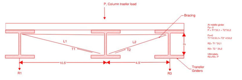
BAretired Thank you for your response. I see some concern in your approach, If we solve this system of equation, it will always end in R1,R3= 0 and R2=P (I'm assuming your second equation was meant to be R2 = P-1.429R3) meaning no contribution from outer girders. I'm using slightly different approach, however the problem I'm running into is that in my middle girder is not contributing anything any the total load P will be just distributed to the outer girders. I think the actual behavior of the system will be somewhere in middle of your approach and my approach based on the stiffness ot bracing and girders, question is how can I capture that?
Girder_dmbjoi.jpg


George We haven't discarded the possibility of using transverse beam completely, we've been hesitant because of connection congestion.

Human909 the stiffness required to meet the deflection criteria is enormous and we couldn't fit any PG with that stiffness in the available depth we have that's the reason of looking into using multiple girders and use combined stiffness with the restricted depth that is available to us.
 
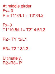
Realized, the calculation in the image above isn't clear. Here is a clearer snap. Also, R2 is R1 in the equations, typo.

Calc_ipbjwg.jpg
 
GOD's HAT said:
I see some concern in your approach, If we solve this system of equation, it will always end in R1,R3= 0 and R2=P (I'm assuming your second equation was meant to be R2 = P-1.429R3) meaning no contribution from outer girders.

That is totally wrong! You can't argue with statics.
It's clear you do not understand my approach, but I am not in the mood to argue about it now.
Beef up the central beam as required and forget about this nonsense.
 
Now I'm in the mood to argue about it.

Let us say that B2 is adequate to carry kP where k is a fraction less than one.
That means B1 and B3 must carry (1-k)P, so R1+R3 = (1-k)P.
But R1=0.429R3 so 1.429 R3=(1-k)P and R3 = (1-k)P/1.429
and R1 = 0.429(1-k)P/1.429 or 0.3(1-k)P.

Suppose k = 0.8 which means that B2 deflects more than it should if the load exceeds 0.8P.
In that case R1 = 0.06P, R2 = 0.8P and R3 = 0.14P, for a total of P.
That is true only if (a) the stiffness of B1 and B3 are consistent with the deflection corresponding to the calculated load and (b) the bracing truss does not deflect.

If B2 can accommodate only 0.4P without deflecting too much,
then R1 = 0.18P, R2 = 0.4P and R3 = 0.42P, for a total of P.
If B1 and B3 are too stiff, this will be conservative.
If the truss deflection is considered, B2 will carry more than 0.4P

I still don't like it. I prefer to build up B2 and leave B1 and B3 out of it.
Rant concluded.

 
GOD's HAT said:
I'm designing a transfer girder which has a tight deflection criteria and the depth of girder is restricted by some ARCH constraints.

If B2 is adequate to carry the load P, and the only concern is deflection, why not prestress the existing beam from end to end, effectively loading the beam with an eccentric axial compression. I am thinking of a Dywidag rod each side of the web, resting on the bottom flange, and connected to a welded plate each end of the beam.

 
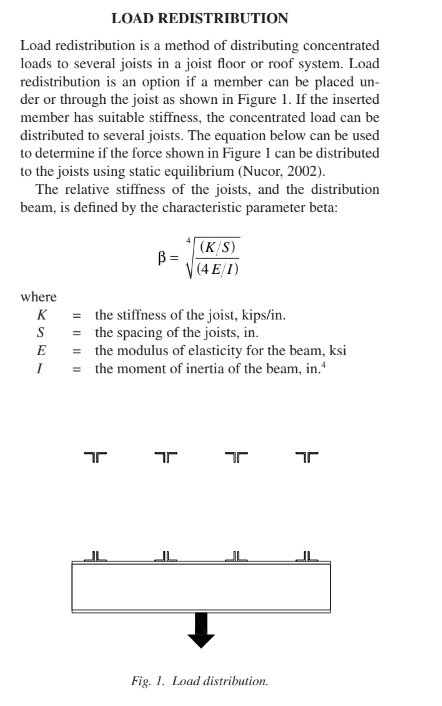
This feels like a common joist problem - I have a load to hang, but my joist isn't strong enough. How can I distribute the load to adjacent joists?
The result is based on the stiffness of the joists and the stiffness of the header. A very stiff header will distribute the load evenly to all the joists. A very soft header will not distribute any load to adjacent joists.
The stiffness of the joist is also based on where you`re applying the load over the length of the joist.

I suggest looking into that procedure for this application.
 
Once20036 Thanks for the suggestion, turns out we looked into similar thing. We ultimately designed bracing systems the a particular stiffness such that it transfers the load we want it to transfer.
 
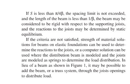
This article may help: James M. Fisher's "Strengthening Open-Web Steel Joists"

Screenshot_2024-05-01_150403_ypbfa6.png

Screenshot_2024-05-01_150409_bpyraf.png
 
Status
Not open for further replies.

Part and Inventory Search

Sponsor