structeng2
Structural
Hello All,
I am working on replacing rooftop equipment on an existing single-story building.
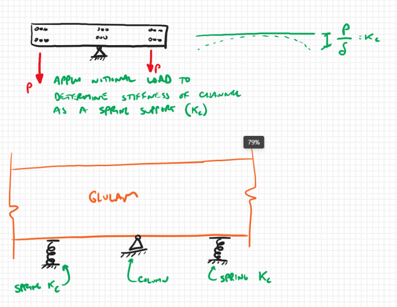
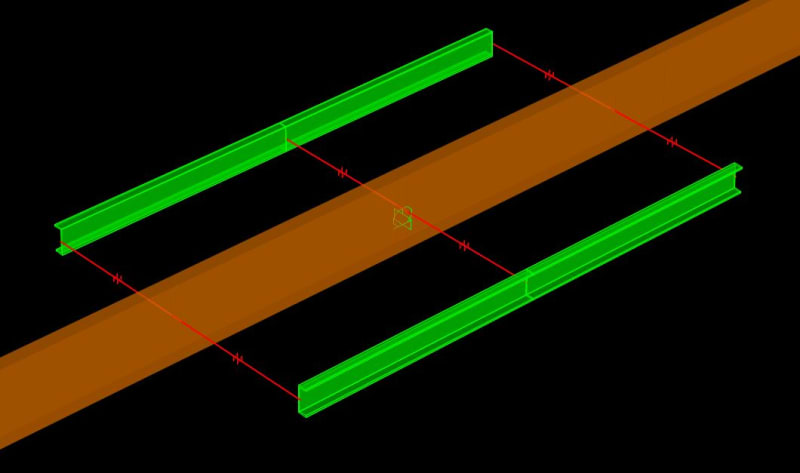
The new RTUs are located along the column line in the middle of the building with supports on either side of the column, attached to the glulam member, increasing the negative moment. In 2010, a retrofit was performed on these glulams, bolting an MC10x25 on either side of the glulam centered over the columns. We are calculating the capacity of the transform section and I want to make sure our calculations are accurate - as I haven't done a transform section in a while. I reviewed this thread, but still wanted input on our situation.
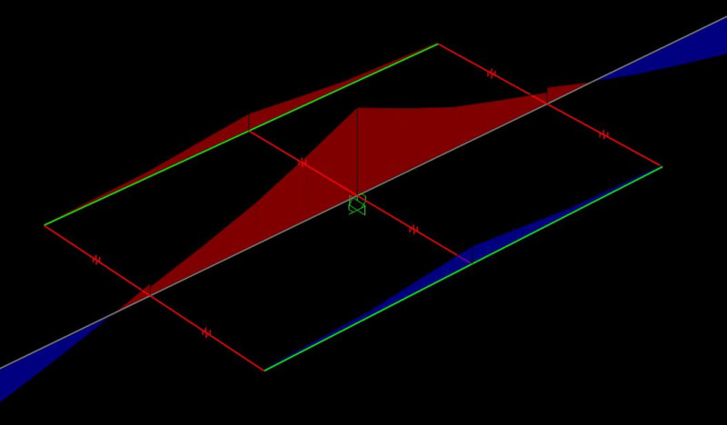
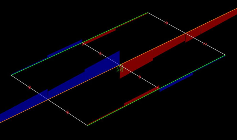
The calculation and diagrams are attached, but here are my questions/thoughts:
[ul]
[li]We transformed the glulam to steel, so we ended up with a very slender steel 'plate' between the two channels[/li]
[li]We got the necessary section properties of the transformed section[/li]
[li]Calculated the steel section capacity using FyZx (Aisc F2-1)[/li]
[li]Based on the ry of the transformed section, LTB does not control because Lb < Lp.[/li]
[/ul]
However, the part that I am confused on is that the transformed section has these tall slender elements above and below the channels. Using Table B4.1b, Case 10, the elements are slender. Maybe I should be using AISC F3?
For what it's worth, the channels on their own can support the RTU's. And we are attaching the RTU frame directly to the channels with a saddle that goes over the Glulam and bears directly on the steel. But I still want to verify our methodology on the transfor section.
Thanks for your input. Looking forward to the discussion.


