Continue to Site

Eng-Tips is the largest engineering community on the Internet

Intelligent Work Forums for Engineering Professionals

  • Congratulations KootK on being selected by the Eng-Tips community for having the most helpful posts in the forums last week. Way to Go!

Glulam compression side notch

Status
Not open for further replies.

YoungGunner

Structural
Sep 8, 2020
98
HVAC subcontractors drilled holes through the top of the glulam. The glulam has (3) 2x plies on top of it that may be cut for plumbing, but the guys cut 3" into the glulam. The glulam is 5-1/8" X 19-1/2" deep and is 23ft long. The beam only supports floor for a kitchen/great room and was increased one size to limit deflection and would fail in flexure if 18" deep. I've already run some stress concentration calcs which amplify the stress well beyond it's capacity. I've already considered telling them to cut it out and put in another beam, such as a dropped steel beam, but looking if anyone has a way of reinforcing this beam first before we go the extreme route.
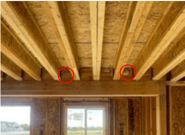
Screenshot_2022-10-06_092558_uuqzi5.png
 
Replies continue below

Recommended for you

The holes look perhaps too large for this, and perhaps in the wrong location. But you may consider this Link.

Maybe a steel element designed to take the compression could be used to reinforce the hole. Would need to go on top of the beam though it looks like because the joists are in the way to put it on the side.

It would fail in flexure if only 18" Deep at the midspan? or at the location of the holes? This might be an important distinction.
 
Just a couple ideas:

1. What kind of tributary area is supported by this? Any justification for a live load reduction? I wouldn't typically allow for this on a small residential build but this looks like a substantial area.

2. How close are these holes to the midspan? What is the Mf/Mr at the given hole locations?

3. Can you attach additional material onto the backside of this beam? If the joist on the other side are parallel, maybe you can install a 18" deep timberstrand or parallam. If joists are perpendicular can you design a steel C-channel to bolt to the face of the beam?
 
I'd expect at the one location it's less of an issue due to proximity to the end of the beam. Shear is usually not an issue with wood beams. I don't see why you couldn't epoxy in new material into the holes and consider the beam as strong as ever in the compression flange. I feel complete removal is likely overkill.
 
driftLimiter is right. If your beam is 23 ft long, this appears to be close to the support, not at midspan.
Also you are talking for the top part of the beam, which ideally is in compression.
Is it simply supported? It appears to be, although photo is not clear.
 
Is the sketch below what you are describing?

glulam-q_wch8dh.png
 
Brad805 - yes, that is the situation we are looking at.

For the other questions - joists are perpendicular on the opposite face, beam is simply supported, the hole to the left is closer to midspan but not quite and the right hole is about 32" from the support.
 
Start with the easy questions first:
1) You mentioned an extra (3) plies at top of beam for plumbing, can you explain this concept further? Is this a custom manufactured glulam where you specified the particular layup/pattern?
2) Your neutral axis is shifted with those holes. Combined with the non-uniform layup pattern of a standard V4 glulam, are you certain you've correctly calculated the allowable moments at these locations? You're neutral axis is going to be pulled very low into the beam due to these factors.
3) Repair is... difficult in wood. This is drastic, but might consider shoring and cutting joists back, and bolting a single piece of continuous steel alongside to carry the moment, and treat the glulam as an element to prevent steel buckling. Bolting pattern would need to be appropriate. Joists would need to be either reattached with something like a DGF hanger (painfully expensive), or the addition of another layer of wood beyond the steel to ledger from. This would require furring out bearing below to support steel and ledger.

Jayrod said:
...consider the beam as strong as ever in the compression flange.
Not sure where you are seeing a compression flange on a glulam?
 
ChorasDen said:
Not sure where you are seeing a compression flange on a glulam?
The top of the beam is in compression correct? Generally speaking we call the top and bottom of beams flanges. Therefore compression flange of the beam. Is it correct to say it this way, probably not. But I bet 90% of the people on here understood what I meant and didn't feel the need to call me out on it.

And I disagree that a repair of this beam would be difficult, assuming that the plumbing can be moved. You should be able to epoxy wood back into the holes and it will be as strong as it was originally. If the hole/notch was in the bottom of the beam, then I'd agree we are in for a bit of a battle, but not at the top of a simply supported gravity only beam.
 
I too do not think this is overly complicated to repair. It surely does not warrant the argument involved in replacing. If they can't move the plumbing, I would look at steel plate. If you were not consulted before cutting you could insist they provide you an engineered design. We did one of these last year. They wanted to cut a hole in a steel beam for high velocity piping. We detailed a solution, and then they found an alternate route.
 
Status
Not open for further replies.

Part and Inventory Search

Sponsor