Continue to Site

Eng-Tips is the largest engineering community on the Internet

Intelligent Work Forums for Engineering Professionals

  • Congratulations KootK on being selected by the Eng-Tips community for having the most helpful posts in the forums last week. Way to Go!

Gravity Only Columns and Beams 2

Status
Not open for further replies.

struggle67

Structural
Mar 29, 2013
116
Hi, it is me again. [smile]
In a concrete building with shear walls, do your columns and beams take lateral loads in these cases (a) wind only (b) wind + seismic? In where I practice, I always heard people say that they let their shear-walls take all lateral loads, and columns are only designed for pure gravity loads. Do you guys do that for your building's design? How do guys do that in your software model? Pinned all column and beam connections or reduce stiffnesses in a separate model created just to design walls without contribution from columns and beams?

I know that there is this requirement in Eurocodes “columns that are not part of the lateral load resisting system shall be designed to maintain the support of gravity loads under the most adverse displacements and deformations imposed on them in the seismic design situation”. By the way, does commercial software check and account for this?

Should column and beam frames take lateral load according to their relative lateral stiffness?
 
Replies continue below

Recommended for you


Could be but not always true.. For example ; Look ASCE 7-10 Table 12.2-1 Design Coefficients and Factors for Seismic Force-Resisting Systems.. You will see structural wall only systems , Dual systems where WITH MOMENT FRAMES CAPABLE OF RESISTING AT LEAST 25% OF PRESCRIBED SEISMIC FORCES
......


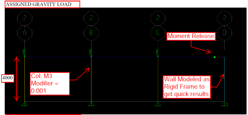
If this question is for gravity only columns, it is simple process .. Either assign pin connections at top and bottom joint of the columns or set bending stiffness to zero..


Not sure i understand correctly.. are you looking for a commercial software with voice recognition so you can say , the defined columns will only be modelled for gravity loading etc..??
 
In a concrete building with shear walls, do your columns and beams take lateral loads in .... Do you guys do that for your building's design?

Yes, if you're designing the main SFRS of your building as Building Frame System.
In case you don't already know, building frame systems are those which use frames to support vertical loads and, shear walls or braced frames to resist the lateral loads.
In this system, however, gravity only members must be able to support gravity loads upto design level lateral displacement.

How do guys do that in your software model? Pinned all column and beam connections or reduce stiffnesses in a separate model created just to design walls without contribution from columns and beams?

Yes, best way to do this is to make a separate model for wall design and reduce the beam-column joints stiffness so that frames don't participate in resisting the lateral forces. Also, reducing stiffness modifiers of columns only, will suffice in most of the cases.

However, for checking the provisions for gravity only columns as per the ACI code, designers usually provide the code specified cracked section modifiers to get member forces at design level displacement.

I know that there is this requirement in Eurocodes “..... situation”. By the way, does commercial software check and account for this?
If i understand the eurocode requirements correctly, there are sort of similar provisions in Aci code for gravity column in high seismic zones. This article will give you an idea about what those provisions are.

And I don't know about the other software packages, but as far as I know, csi softwares don't perform such checks. Design engineer is responsible to manually check those provisions.

Should column and beam frames take lateral load according to their relative lateral stiffness?
Well, If you want both rcc frames and shear wall to resist lateral loads based on their relative stiffness, then it's better to properly design them as a shear wall-frame interactive system or a dual frame system.

That being said, Rcc frames designed to resist gravity loads only and detailed properly as per the code specific requirements can provide adequate ductility when laterally loaded upto design displacement.


Thank you very much Blackstar123 & HTURKAK,

Blackstar123 said:
es, best way to do this is to make a separate model for wall design and reduce the beam-column joints stiffness so that frames don't participate in resisting the lateral forces. Also, reducing stiffness modifiers of columns only, will suffice in most of the cases.

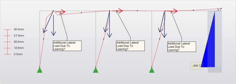
I created a very simple frame to test. A wind point load of 50 kN is applied at top of the 4m high leftmost column/frame. All beam/column connections are pinned. Please see the picture below. The moment in the shear wall (~600 kN-m) is 2 times higher than I expected 300 kN-m (1.5 x 50 x 4). I was doing 1st order analysis only. I guess it is because of the leaning effect of the simple-frame on the shear wall. Am I right? When I do hand calculation, I can include that effect by amplifying with a factor.

In practice, how do you or a commercial FEM software include this effect? I sketched the forces in the diagram. Is it something like that?

Capture_pwvcu9.png
 
struggle67 ........ [b said:
A wind point load of 50 kN is applied at top of the 4m high leftmost column/frame. All beam/column connections are pinned. Please see the picture below. The moment in the shear wall (~600 kN-m) is 2 times higher than I expected 300 kN-m (1.5 x 50 x 4).[/b] I was doing 1st order analysis only. I guess it is because of the leaning effect of the simple-frame on the shear wall. Am I right? When I do hand calculation, I can include that effect by amplifying with a factor...]

Apparently your model and analysis violates basic equilibrium rule of statics.. I think there are hinges at the mid points of beams and columns..If so, your model is label ....
 
A wind point load of 50 kN is applied at top of the 4m high leftmost column/frame... The moment in the shear wall (~600 kN-m) is 2 times higher than I expected 300 kN-m (1.5 x 50 x 4)
Overturning moment at the base of wall should be 50x4 = 200 kN-m. There is something wrong with your model if it's giving you total moment at the base more than this. Also, what does the factor of 1.5 accounts for?

I guess it is because of the leaning effect of the simple-frame on the shear wall. Am I right?]
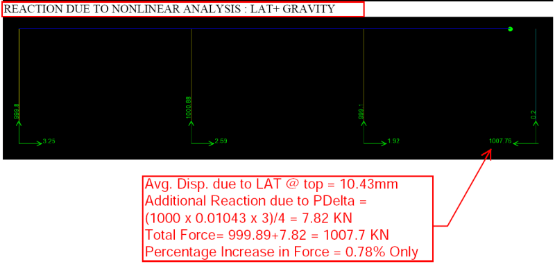
I don't think so. The effect of leaning on shear wall will not be as high as 2 times the expected force. And software will not capture this effect unless you perform non linear p delta analysis.
 
Sry Sry My bad. There is another load accidentally applied under dead load case.[angel]
 
I don't recognize the software, so I can't really help you to find out what's causing the problem.
But I quickly made a similar model in sap2000 and it's giving me the expected results.

image_yq164h.png


image_xw8xx7.png


image_phe0by.png


image_y2gnkf.png
 
Status
Not open for further replies.

Part and Inventory Search

Sponsor