Continue to Site

Eng-Tips is the largest engineering community on the Internet

Intelligent Work Forums for Engineering Professionals

  • Congratulations MintJulep on being selected by the Eng-Tips community for having the most helpful posts in the forums last week. Way to Go!

Grid connected DG - Model for estimating Steady State Voltage Rise in Point of Common Coupling (Pcc)

Status
Not open for further replies.

hnes

Electrical
Jun 23, 2017
3
Hi!

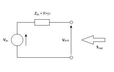
According to the book "Renewable Energy on Power Systems" by Freris & Infield, the voltage rise due to injection of power in pcc can be estimated from the Thevenin equivalent representing the network "upstream" pcc (Figure 1). The Thevenin voltage can be taken as the nominal voltage in the pcc, and the Thevenin impedance
is given by Z= V/√3⋅Isc (1).
Capture_vp2tjv.jpg

Figure 1: Thevenin equivalent

I've got some measured fault current values (three phase) for different Pcc's in different LV radial distribution networks, and want to make an estimate of the voltage rise in each Pcc based on the calculated source impedance in formula 1. This is pretty straight forward according to the mentioned literature, but there is something i don't get:

Is the fault current in the Pcc depending on the numbers of other buses in the LV radial? For me it seems pretty obvious that the impedance seen from the Pcc with DG is lower if your neighbor has a big demand of power, and thus the voltage rise in the Pcc will become smaller (?). I don't get how this Zth calculated from the Isc can be used if this is not the case.

Thanks!
 
Replies continue below

Recommended for you

Power from your generator: S1phase = Vln x conj(I) = S3phase/3.


I = (Vgen - Vutility)/ Zthev

S1phase = (Vgen x conj((Vgen - Vutility)/Zthev))

You know S1phase, Zthev, and Vutility. Solve for Vgen

This will be worse case with no load.

If you want to study the voltages when you have loads, I think you probably will want to use software.
 
If you draw in the system impedance in series with a voltage source to the right of your diagram, then, if you measure fault current at the PCC, you need to consider what the system (other buses) supplies to the fault.
 
Hi!
Thanks for replying, HamburgerHelper. I've been busy this weekend, sorry for the late response.

My question is not how to find Vgen (or Vpcc), but the "correct" value of Zthev (or first of all understand it).

And hello magoo! I have to make some clarifications, seems like my explanation was confusing:

The Thevenin equivalent is the network, Snet means produced power minus used power (net) from the DG (PV, wind, CHP, etc...). The fault current is measured in the Pcc, that's the interface between the grid operator and the consumer (and due to DG, manufacturer).

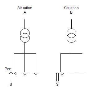
So my question still stands, but i can try to clarify it with a figure:
sitab_ndhl1t.jpg


Is the fault current/level in the Pcc depending on the numbers of other buses in the LV radial (situation A vs. B) ? For me it seems pretty obvious that the total source impedance seen from the Pcc (in a thevenin equivalent) is smaller if your neighbor has a big demand of power (i.e. one or both neighbor buses in situation A have a big power demand), and thus the voltage rise in the Pcc will become smaller (?). Said in another way; How does the topology of the LV distribution network affect the source impedance? Bigger impedance seen from the Pcc = bigger voltage rise (formula 1, post 1) - but if your neighbor in some way uses all your PV-made power, should this impedance then be smaller?.
 
Your neighbours heavy use will create a voltage drop in the radial. That drop will be dependant on the grid impedance. Even if all your power goes directly to your neighbour, you will offset some of that voltage drop, based on the grid impedance.The change in voltage at the PCC will depend on a change in current on the radial. Injecting power will change the current in the radial and that change combined with the grid impedance will determine the voltage change at the PCC.

Bill
--------------------
"Why not the best?"
Jimmy Carter
 
In many short circuit studies, the effect of load is ignored base on a few factors:
*Fault current is often 10x or more than the nominal current, so the resulting error is less than 10%.
*Fault current is mostly reactive, whereas load current is mostly real. When doing the vector math, the real component often has a very small impact on the overall fault magnitude.
*We like a single number as an answer, but including the whole range of possible nominal loads would require many more fault simulations.

Many fault calculation software packages can calculate faults either with or without nominal loading. The big challenge is creating the nominal loading basecase(s).

 
I am confused. First I understood that you wanted the voltage rise at the PCC.
How did fault currents get involved?
As bacon4life pointed out. Load currents are mostly real and fault currents are mostly reactive.
Using the system impedance to calculate the voltage drop or rise will result in a directed value of voltage and the direction will be mostly sideways. You cannot just numerically add or subtract this value from the original PCC voltage.

Bill
--------------------
"Why not the best?"
Jimmy Carter
 
The Thevenin equivalent hnes asked about uses short circuit current:
Z= V/√3⋅Isc (1)

hnes-The book is correct that the voltage rise can be estimated using the equivalent. If you need a more detailed answer, you would have to include a more detailed model that does account for neighboring loads.

By measured fault current values, were they actually measured? Or do you mean calculated? Depending on the kind of study the protection engineer was performing, they may have provided different short circuit values such as:
*Maximum likely future fault current( including proposed future projects) for the purpose of specifying equipment withstand ratings.
*Maximum fault current(including closed feeder/bus ties) for the purpose of setting relays.
*Fault current in normal circuit configuration for the purpose of setting relays.
*Reduced fault current for arc flash studies.
 
Waross: Thanks for the reply! In the first post i wrote that i didn't understand how you could estimate the voltage rise from the formula when not considering other power sinks in the radial (and the impedance in the formula is calculated from the fault current). But bacon4life pointed things out.

Bacon4life: Thanks! Your last post was very informative.

I have one more question:

When estimating the voltage rise, some books/reports/literature in general use only the grid impedance between the distribution transformer and the Pcc, and not the "whole" source impedance (like the book I mentioned). Is his because the impedance upstream from the distribution transformer is pretty small compared to the LV impedance?
 
Most distribution systems have voltage regulators, either for the whole substation bus or for each feeder. If this is the case, you are may only be concerned with the voltage rise on the distribution feeder because the voltage at the beginning of the feeder would be kept constant by the regulators. If the regulators use line drop compensation, you may have to include the regulator controls in the calculation because the DG will change the voltage at the load side of the regulators. This is particularly true if the DG causes reverse power through the regulator.
 
Status
Not open for further replies.

Part and Inventory Search

Sponsor