Eng-Tips is the largest engineering community on the Internet

Intelligent Work Forums for Engineering Professionals

  • Congratulations waross on being selected by the Tek-Tips community for having the most helpful posts in the forums last week. Way to Go!

Grid Resistor Design

Status
Not open for further replies.

1366060

Mechanical
Jul 10, 2012
25
0
0
IR
Hello

I need to design a Grid Resistor for a Given electrically driven Haul truck.
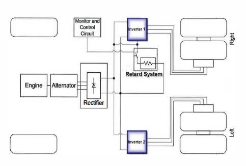
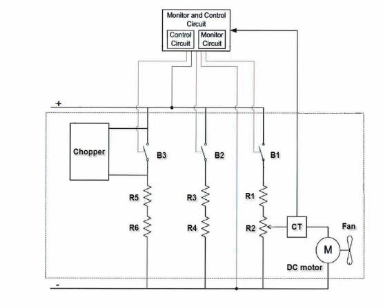
we have two 1400Hp traction motor for propulsion. in retarding mode they will, of course, generate some more power, let's say around 1600. considering these two there will be up to 3200 HP in retarding mode. We need a resistor that would cope with and dissipate such a power in the form of heat energy.

So, does anyone know about know-how of designing and testing a Grid resistor for an electric mining truck? what parameter should be taken into account? what are governing formulas and physical laws?

Any would comment be appreciated.
 
Replies continue below

Recommended for you

You will need an integrated system that leans heavily on high velocity fan driven air across the resistor. You need to calculate the power dissipation and not exceed the per foot dissipation allowed by the resistor element.

There is likely a whole bunch of lab work and trial and error that will go into your system. I expect many do-overs and failures to hassle you. I would go to a company that does 'dynamic braking' systems and get their expertise on-board.

Consider buying a locomotive dynamic braking unit (used) and reverse engineering it into your application.

Keith Cress
kcress -
 
Dear itsmoked

Thanks for your reply

I know some of these companies but because of some issues, I need to go through reverse engineering a current model of Grid Resistor for a specific model of truck.

But, as you predicted I have experienced failure and this time I want to go through principle, so that reduces the possibility of failure as much as I can. Unfortunately, no I have found no text on Design Principle of Grid resistors.

 
Talk to Chromalox.
Link
edu_mlmyj6.jpg

Chromalox has standard units up to One Mega watt. I am sure that they will be able to addapt an "Off The Shelf" unit to suit your needs.
Don't build it if you can buy it.
Quicker.
Cheaper. (Probably)
More dependable.
There is seldom a need to re-invent the wheel.
Bill
--------------------
"Why not the best?"
Jimmy Carter
 
Agree with the others - buy the DB unit from an established manufacturer. You'll probably have to buy the resistor elements anyway, or are you looking at producing your own resistor elements? Cutler-hammer used to manufacturer slotted grid resistors, but when they sold their resistor operation to Cressall the designs changed to an edge-wound spiral design mounted on a ceramic former which was more robust and had higher dissipation per unit volume. I had this misfortune of turning an C-H grid resistor into a 200kW filament lamp which for a fraction of a second was brighter than the sun before it broke up in a ball of blue fire. [surprise] The replacement was the edge-wound type, but I never found out how good a lamp it made.

A couple of other vendors to consider: Mosebach, or Cressall.
 
Dear ScottyUK

thanks for your reply and introducing supply sources.
actually, thanks to hours of searching the net regarding this issues, I know about supplier very well. Further, the end user of resistors also knows about suppliers. nonetheless, they are not willing to supply from these sources(Given that the OEM is not available) and want to build resistors technology in their organization. as a project, build the resistor have been assigned to me. I have reverse engineered and built the first sample, but it crashed during the test. I probably know the error source;

As I have selected the resistor element thickness 0.5mm lower than the original design, and it caused the current density increase dramatically and produce extra heat. besides according to electrical resistance formula, R=p*L/s, reducing element cross-section will result in increased resistance. So the cooling Fan which is being fed by resistor passing current will not start or will work with lower RPM. ( in the attached picture you can see the schematic diagrams, where M).
To reduce the uncertainties, as it occurs always in Reverse Engineering Process, I want to find the design text and scientific/engineering references on this design issue. I have found two textbooks, named; "Propulsion Systems
for Hybrid Vehicles, By John M. Miller" and "Modern Electric Vehicle
Technology, by C.C Chan". Hope they work and help me out.

Retard_System_foahfl.jpg

Retard_system1_glglww.jpg
 
Status
Not open for further replies.
Back
Top