Eng-Tips is the largest engineering community on the Internet

Intelligent Work Forums for Engineering Professionals

Grid scale BESS inverter question 2

Status
Not open for further replies.

Latango

Electrical
Dec 12, 2006
28
0
0
AU
I have tried to find this information online, but I can't seem to find a difinitive answer.

In our country we are starting to install quite a few large battery systems to try to cut back on peaker plants, along with many others I assume. I am curious though, at the 100MW+ size installations where there are hundreds of battery units and dozens of inverters, how do they control the power flow?

The BESS I have been working at uses 4 x 4MWhr/2MW battery units feeding into 1 4MW inverter (Power Electronics PCSM 33kV), lots of which are joined together and then fed into a stepup transformer feeding directly into the grid. Everything in the installation makes sense to me (a non engineer, electrician only) except I can't get an answer on how the inverters control the power flow to either charge or discharge the batteries.

Do the inverters simply raise or lower the voltage to above or below the grid volts? Or is it a very slight frequency or power factor shift?

This isn't a critical question, it's just curiosity on my part. If anyone can help educate an ignorant sparky I would be very appreciative.
Thanks guys/girls.
 
Replies continue below

Recommended for you

There’s a plant controller that tells each inverter what to do. Hopefully it provides a consistent set of directions instead of some charging while others discharge.

When one this sentence into the German to translate wanted, would one the fact exploit, that the word order and the punctuation already with the German conventions agree.

-- Douglas Hofstadter, Jan 1982
 
I'm sure that the software would make them all work hand in hand, unless there's a fault on a battery or something.

The question that I can't find the answer to is HOW does the inverter change the power flow? Is it as simple as voltage higher than grid = power flows out (discharge into the grid) and voltage lower than grid = power flows in (charging from the grid) or is it something to do with the sync of the grid and inverter?

 
That’s all in how the IGBTs (or whatever they’re using these days) are gated. A four quadrant inverter can do whatever is needed. Firing angles vs system angles.

And don’t be so confident about the plant controllers, particularly during commissioning.

When one this sentence into the German to translate wanted, would one the fact exploit, that the word order and the punctuation already with the German conventions agree.

-- Douglas Hofstadter, Jan 1982
 
I'll start with an explanation of how parallel generators control the flow of power.
Forget voltage.
Power flow is controlled by relative phase angles.
Imagine two generators working in parallel and sharing the power equally.
If angular position indicators were fixed to the end of each shaft, they would both be in identical angular positions.
Index lines and a strobe light will be useful.
Now the prime mover is increased to one generator. This may be opening a throttle, opening a steam valve or opening a water gate.
That generator will move a few percent or a few degrees ahead of the other generator. That will cause it to pick up more of the load.
As one generator picks up load, the other generator sheds load.(The load is applied externally and is assumed to be constant for this example.)
If this process is taken too far, then one generator will start to motor the other generator in addition to supplying all of the load.
This is assuming that this condition is within the capability of the generator and prime mover.
So, advancing the sine wave of one generator, relative to the sine wave of the other generator will cause the advanced sine wave to pick up more of the load.
Another way to visualize it is to look at or visualize a scope with traces from both AC tachometer generators superimposed.
As one prime mover is advanced, you will see the corresponding trace advance or shift ahead of the other trace.

Now lets consider inverters.
A free running inverter generates a sine wave.
A grid tied inverter generates a sine wave in step with the grid.
If the control algorithm times the inverter sine wave to start just ahead of the start of the grid sine wave, the inverter will feed power into the grid.
The controlling signal tells the algorithm how much power to produce and the algorithm triggers the start of the sine wave at the correct instant to produce the amount of power needed.
Yes, I know;
The inverter output is actually a Pulse Width Modulated output, but that filters to a sine wave and I am trying to keep the explanation simple.

--------------------
Ohm's law
Not just a good idea;
It's the LAW!
 
As grid inverter it's an ac power device connected in parallel with grid, from control section may choose power flow direction.
In inverter control section (firmware and circuits) may implement active and reactive power control level and direction.
After control section make all calculation, obtain needed PWM signals to send to power section, depending of inverter topology, number of phases and other details.
A short video that explain on grid inverter active and reactive power control:
 
davidbeach: I'm not on the commissioning team, only construction, thankfully :) PE have their own techs doing the hard stuff, so I imagine they're doing the right thing.

waross: Perfect, that's what I thought might have been the case, but lacked the language and understanding to express it. Thanks very much for the concise explanation in laymens terms, "synch" was the only way I could think to visualise it.

iop95: That video was very helpful also, though I had to watch it a couple of times because my grasp of the theory is not as strong as it should be. It's getting better now though :)

Thanks guys, nothing worse than seeing something and not knowing how it works. Much appreciated :)

 
So if voltage has no direct effect on power sharing what does it affect?
Small differences in voltage control Reactive Rower flow.
Large differences in power flow may lead to circulating reactive current between generators or the grid.
Sometimes that is a good thing.
Example:
A third world city ran on diesel generator power.(Long long ago and far far away, when diesel fuel was cheap.)
Then the country constructed a large hydro-electric generating plant and ran a transmission line across the country to service the large city.
The diesel plant was abandoned but not torn down.
Eventually the city outgrew the capacity of the transmission line.
The capacity of the conductors and circuits that most of us are familiar with is limited by the heating casued by the flow of current through the resistance of the conductor.
Often the capacity of a long transmission line is limited by the ability of the substation transformers On-Load-Tap-Changers to compensate for the voltage drop in the line.
But there is another difference.
The impedance of the circuits we are familiar with is mostly resistance.
Not so with transmission lines.
The impedance of a long transmission line may be be more reactive than resistive. That is Inductive Reactance.
The capacity limit on a long transmission line may be limited by the voltage drop caused by inductive reactance.
In the city in question, the old diesel plant was started up and put back into service.
Was this to provide the power shortfall?
No, by this time diesel fuel was too expensive.
The diesel plants were overexcited (The voltage was increased) to cause reactive current to flow back into the grid.
But with overexcited gen-sets this was capacitive reactive current rather than inductive reactive current.
This capacitive reactive current offset of cancelled the inductive reactive current in the transmission line and eliminated the reactive voltage drop of the line.
The effective capacity of the line was assured well into the future.
The point of this discourse?
Voltage adjustments control reactive power, not real power.
Sometimes this is a good thing.

By the way, this is not the only possible solution.
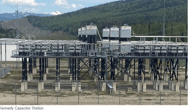
I once worked on a project installing capacitor banks in series with a 500,000 volt transmission line to offset line reactance and increase the capacity of the line.
500_000_Volt_Capacitor_Station_jh0abi.png

The individual capacitors were 17000 Volt rated. The individual capacitors were connected in series/parallel to get the needed current and voltage ratings needed.
In the picture you can see the stacks of capacitors mounted on insulators and stacked three high on smaller insulators.
The entire platform for each phase is supported on the large vertical insulators.
Three phases and six platforms and we only broke one of the vertical insulator strings during construction.


--------------------
Ohm's law
Not just a good idea;
It's the LAW!
 
In general I am one of the guys building and testing that sort of gear, not designing them. This post (using an old diesel generator in place of a cap bank / shunt reactor setup / however else line reactance is combatted) certainly highlights (to me anyway) the difference in knowledge levels between experienced engineers and even experienced electricians. I realise that we never stop learning but sometimes I wonder if I even have enough years left in me to learn enough to not have to ask basic questions all the time. Thanks for taking the time, Waross. It's much appreciated.
 
I’m sure that Bill is completely correct in what he said about those Diesel units. But, how often did they then need to be connected to a load bank? Or were they so well broken in by then that they could tolerate the wet stacking? Electrically it’s a clever solution, but how well did it work mechanically?

When one this sentence into the German to translate wanted, would one the fact exploit, that the word order and the punctuation already with the German conventions agree.

-- Douglas Hofstadter, Jan 1982
 
David said:
Electrically it’s a clever solution, but how well did it work mechanically?
I wondered that myself, David.
My exposure was social interaction with a utility engineer and driving by the site.
But from experience, I have experienced wet stacking several times on new sets.
More than once a new standby set, under light load pumped out so much oil in a few hours that it shut down due to low oil pressure.
Not a nice thing to do to a brand new set on the first run.
I installed one set that generally ran at the most 25% of capacity and often less.
However, there was one large motor that took all the gen-set had to get started.
The vendor's rep demanded that I load bank the set for a week to seat the rings.
No load bank,no warranty.
On the other hand I have had a couple of old (admittedly small) sets that ran much of the time with light loads and never had an issue with wet stacking.
This is sets with over 15,000 hours.
On the other hand I once was associated with an old diesel truck that pumped oil at a furious rate when not under load.
When the engine started to pull, all the oil that had been pumped into the exhaust system burned off in the exhaust system and produced clouds of black smoke.
If the sun was behind you, the sun went out.

Your point is well taken David, and my answer is:
I don't know.
I don't know if wet stacking was an issue.
I don't know what mitigating techniques were used, if any.
And, yes, I wondered as well.

--------------------
Ohm's law
Not just a good idea;
It's the LAW!
 
They needed a clutch so that the Diesel engine could spin the "generator" aka "synchronous condenser" up to speed and synchronize it with the electrical system, then disengage mechanically and the engine could shut down. The condenser could then spin along contentedly drawing in a bit of real power and converting it to a much greater amount of reactive power.

When one this sentence into the German to translate wanted, would one the fact exploit, that the word order and the punctuation already with the German conventions agree.

-- Douglas Hofstadter, Jan 1982
 
They needed a clutch

Actually, just a gearbox that would smoothly disengage at speed no load would be all that was needed in that application.

Engagement of the gear box would always take place with the prime mover and generator at rest prior to start, so, depending on the size of the units, at most a small Bendix-coupled electric motor could be used / might be needed to slowly rotate the generator so as to line up the gearbox teeth for engagement. Alternatively, and more simply, with the engine cylinders decompressed and the engine pre-lubed, the engine starting mechanism could be engaged momentarily, perhaps at reduced voltage if electric, to rotate the engine just enough to enable the gearbox to be engaged.

A clutch would be overkill, as clutches are designed to repeatedly de-couple and re-couple a prime mover from its load; but in this case there would never be a need to "clutch in" the Diesel engine to the spinning synchronous motor - unless, while the synchronous condenser was in service, the unit was emergency dispatched into generation mode to meet an unexpected energy emergency, requiring the Diesel engine to be started . . . hmmm, maybe a clutch isn't such a bad idea after all . . .

I'd be concerned though that since the Diesel engine was normally never loaded up to any degree that wet stacking would become an issue.

CR

"As iron sharpens iron, so one person sharpens another." [Proverbs 27:17, NIV]
 
Wet stacking is most often caused by the rings not seating perfectly.
Under load, combustion pressure is ported to the cavity behind the compression ring.
In an older engine, the rings are typically well worn in to a perfect fit from millions of cycles.
If the rings are worn to the point of wet stacking, the engine may be well past the need for a top end overhaul.
Mechanical was not my wheelhouse, but the mechanical guys did a top end rebuild every 15,000 hours in the small diesel plant.
It may not take a high percentage of power to avoid wet stacking.
And politically, the operators would be well paid for any real power generated.

Clutches?
Special over-running gearboxes?
Nothing ever developed, but my friend at the national utility and myself had an informal conversation about the possibility and feasibility of removing a generator end from an old diesel set and installing a flat plate and bearing to support the front end of the generator end.
The set would then be started either with a pony motor or as a synchronous motor.
With a typical automotive style clutch, the pilot bearing locates and centers the short shaft and clutch disk.
The pilot bearing is also intended for short time service. It only turns when the clutch is disengaged.
The same for the throw-out bearing.
The pilot bearing may not be sufficient to support the front end of the generator end.
So, with a clutch and possibly with a special gearbox, some means may be needed to support the front end of the generator.
Once that issue is solved, why go further.
Just add a small pony motor and a drive belt.

--------------------
Ohm's law
Not just a good idea;
It's the LAW!
 
Status
Not open for further replies.
Back
Top