ZeroStress
Structural
- Oct 15, 2012
- 19
Hello
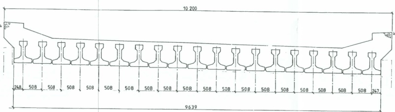
I am currently assessing a bridge deck by grillage analysis. The deck consists of T4 prestressed beams closely spaced together (500 crs) and fully infilled with insitu concrete with 75mm topping.
I have modelled the longitudinal grillage member representing the main prestressed beams and assigned the relevant section properties.
However, I am confused in what should be the section properties for the transverse members. In the case of a prestressed beam with just a flange insitu concrete (not full depth infill), the transverse section is represented as the flange depth x spacing of transverse members. Is the same principle applied to the fully infilled deck i.e. total depth of the T4 beam and topping x spacing of transverse members?
If I assign the section properties based on full depth of the section, I get a heavily stiff deck in transverse direction which is eventually transferring most of the load towards the edge longitudinal member eventually over stressing it.
Could anyone please advise?
Thanks