Continue to Site

Eng-Tips is the largest engineering community on the Internet

Intelligent Work Forums for Engineering Professionals

  • Congratulations KootK on being selected by the Eng-Tips community for having the most helpful posts in the forums last week. Way to Go!

Grinding and Shot Peening

Status
Not open for further replies.

NZHEng

Mechanical
May 22, 2019
8
Hi
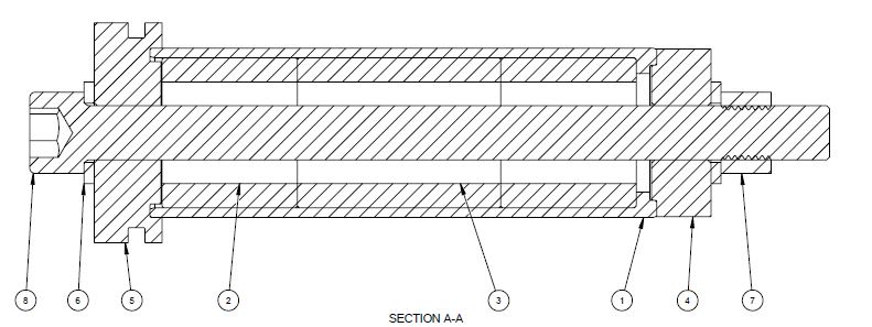
I am designing a fatigue resistant shear pin. The pin is essentially a tube with three plugs lightly pressed into the bore. The plugs control the shear planes (double shear).
The tube is 50 mm OD (g6), 44 mm ID (H7), 140 mm long. The material is 4140T.

Due to the interaction of the plugs there are high cyclical stresses both on the ID and OD.
To maximize fatigue life I had intended to grind or hone the ID to 0.2-0.3 Ra, and grind the OD to 0.2 - 0.4 Ra.

I would also like to shot peen both tie ID and OD. I am considering 0.006"A to 0.008"A intensity at 100% coverage to AMS2430.
I understand the shot peening must be the last operation and have located a workshop which can do this.

However I am wondering if the surface finish prior to shot peening is wasted money, given a shot peened surface is necessarily rough.
The workshop indicated a good surface prior to peening is still advantageous in order to avoid rolled burrs at a microscopic level, or significant machining marks the peening would not obscure.
The chart here seems to support this: [URL unfurl="true"]https://osk-kiefer.de/wp-content/uploads/16-shot_peening_and_coarse_grinding.pdf[/url]

Does anyone have experience with such a combination?
 
Replies continue below

Recommended for you

The geometry is not clear to me from your description.
Nor is the surfaces of the cylinder and three pins where you are thinking about the shot peen. (ID of the tiny cylinder holding the pins?)
 
Pin_Section_dzckif.jpg


This may help clarify.
 
I would recommend a publication from Society of Automotive Engineers called "Fatigue Design Handbook". This should have a chart showing max stress vs. cycles to failure for various surface finishes.
Hope this helps.
 
NZHEng,

Since your L/ID is much greater than 1.0, you probably will not get a satisfactory result with conventional shot peening. The shot impingement angle on the ID surface will be very shallow. Shot impingement angle is very important, with 90 deg (perpendicular to the surface) being ideal.

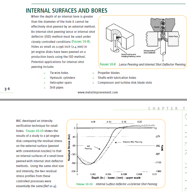
You can use a shot peening technique like those shown below (lance or deflector) on your tube ID surface. The graph gives a comparison between external shot peening and internal shot peening using a deflector.

You might also take a look at roto or flap peening the ID surface.

Another possible option is roller burnishing the ID surface.

It is common practice to finish grind/hone a surface after shot peening. However, the amount of surface material that can be removed without affecting fatigue life is limited based on depth of the residual compressive layer. You can find more information in shot peening specs like AMS2432.

Hope that helps.

internal_shot_peening_lud6i0.png
 
NZHE...

This Pin Assembly' has superficial resemblance to large shear pins used in aircraft shear-critical [wing-fuselage, stabilizer-to-center-section, pylon-to-wing, etc] joints...

However, the concept of internal 'stacked shear-plugs' is very 'unique' and appears to make the joint very complex. Hmmmmmmmm.

Regards, Wil Taylor

o Trust - But Verify!
o We believe to be true what we prefer to be true. [Unknown]
o For those who believe, no proof is required; for those who cannot believe, no proof is possible. [variation,Stuart Chase]
o Unfortunately, in science what You 'believe' is irrelevant. ["Orion", Homebuiltairplanes.com forum]
 
Thanks all for your feedback.
Unfortunately roller peening doesn't seem to be available in New Zealand where I am based, though I have heard very positive things about the finish and accuracy of the process.
Airbus New Zealand have taken a look at the part and agree they have the necessary equipment here.

Regarding the design of the shear pin, I agree it is complicated for a shear pin design, however provides significant fatigue advantages.
It is based on an old patent which was developed by NASA. Link
 
NZHE... for what it's worth...

Is this a 'tried-tested-proven' shear-pin design... in current use... not just a patent?? Properly designed shear-pins can be both 'simple' and 'fatigue durable'.

Reason I ask is 'devil's in the details'... and I see inherent detail-design/fabrication issues that required explicit care to ensure proper function. And, in general, the apparent complexity make me very uncomfortable based on working experience with these beasts.

I have dealt with similar shear pins for MIL acft wing-to-engine-to-pylons. Based on discussions with the OEM, the philosophy of the early jet-age was to allow engines/pylons to 'shear and fail-away safely in a prescribed-manner' in over-load circumstances.... which lead to catastrophes due to unintended consequences. The current philosophy is to hold-on to the engine under most circumstances.

Regards, Wil Taylor

o Trust - But Verify!
o We believe to be true what we prefer to be true. [Unknown]
o For those who believe, no proof is required; for those who cannot believe, no proof is possible. [variation,Stuart Chase]
o Unfortunately, in science what You 'believe' is irrelevant. ["Orion", Homebuiltairplanes.com forum]
 
Status
Not open for further replies.

Part and Inventory Search

Sponsor