Eng-Tips is the largest engineering community on the Internet

Intelligent Work Forums for Engineering Professionals

Ground Fault relay tripping off the MAIN intermittently - Any immediate or temporary help to offer? 1

Status
Not open for further replies.

bdn2004

Electrical
Jan 27, 2007
792
0
0
US
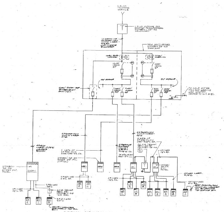
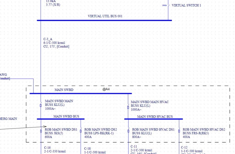
There's a 480Y/277V utility feed coming into a plant's switchboard. It divides between two 1000A Pringle Switches that serve as the Mains to the distribution panels.
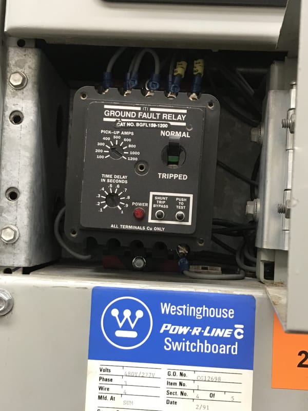
They are coupled together. There's a ground relay set to 300A, .4 seconds on each 1000A main. Both are tripping - sporadically but at the same time when it happens.
It's tripped off once last month, once this month. It's reset and held.

There's obviously a ground fault, but who knows where.

Is there any advice we could offer, to try to make sure until they figure out exactly what's the issue, that it won't trip off ?

Ground_Relay_Tripping_SL_jhguev.jpg
 
Replies continue below

Recommended for you

How is the current signal to ground relay wired - is it through residually connected phase CTs? In a three phase, 4-wire distribution, ground fault protection relay should be summing up all three phase as well as neutral current, to account for unbalanced loads downstream.
Could it be that there are single phase loads downstream and the ground relay is measuring unbalance currents and not the ground fault current?
I cannot imagine ground fault protection with 300A pickup operates without a 'bang' anywhere in the downstream. If there were truly a fault, I would expect some tell-tale signs, with that kind of current setting and 400ms of time delay setting.
 
I agree with Raghunath that the current sensing method is very important.
Also please check whether the subject earth fault device setting is coordinated with the downstream devices.
 
I don’t have a schematic of the incoming mains. All I have is pictures of the ground relay and the outside of the switchgear. It does have a digital ammeter on the door also that measures all three phases. I would therefore assume it is a residually connected circuit. And that 300A setting looks reasonable for that type of relay on a 1000A circuit. Do you agree ?
 
I've lost track of how many times someone believed a relay or breaker setting would limit the fault current to that value, yet it doesn't.

I too doubt you could get an actual ground failure without some sign it happened. Remember, with a solidly grounded system you don't just get the 300A ground fault current for 400mS, you get the L-N fault current for 400mS. That will be much higher than 300A and enough to cause serious damage to whatever fails to ground.

I believe 300A is the code required level. Still it's about as reasonable as any other setting when considering a ground fault will cause L-N fault current to flow and you just need to detect when that happens.

There must be something "funny" going on with the ground fault relays on 2 different distribution branches tripping at the same time.
 
That's a good point... a L-N fault - I checked it that would be 12.3kA of fault current in this system.
The line fuse would blow close to the bus...But what if it's way down the line and the fault current is very little ?

So as RR stated...so it could be an imbalance on the loads? For example- Ia, Ib = 500A and Ic = 800A
This condition can cause a residual relay to trip?

Maybe they've changed something in the last few months.
It is occurring in the winter. And this equipment does feed outdoor HVAC equipment.

Any other ideas ?
 
Current imbalance should not cause a ground fault trip.

Neutral currents could be cause IF the ground fault relay doesn't include measuring (summing) the neutral current with the phase conductors.
 
If “coupled” means that there is a connection between the two of them down stream of the sensing then all it takes is unequal load sharing between phases. There should not be any downstream connection for exactly that reason.
 
"Coupled together"

As shown on the single line...the two Main Pringle Switches are part of the same line up, but are metered separately for some reason.
It's a four section fused switchgear. An incoming section with a ground relay, and an ammeter. And another section on the outside for the two fused distribution feeders. X 2.

The grounds are all tied together at that point.

And as stated....BOTH Ground relays are tripping sporadically.
 
I'm still not clear what is meant by "coupled". Where are the ground relays? What do they trip? Are the distribution feeders from MAIN SWBD BUS & MAIN SWBD HVAC BUS ties together so that a ground fault on one would result in current through both MAIN SWBD MAIN & MAIN SWBD MAIN HVAC?
 
Sorry ... coupled is just a term I used for the common incoming bus.
We are getting some pics of the inside, which we don't have right now.

There are two ground fault relays, and each open their respective main (MAIN SWBD MAIN & MAIN SWBD MAIN HVAC). I'm not familiar with how a Pringle Switch operates automatically, but this is what is opened. The incoming power at 480V is from the Utility.

In looking at the distribution loads - the MAIN SWBD BUS feeds bunch of lighting panels & MAIN SWBD HVAC BUS feeds Air Handlers, Heat Pumps and Electric Heaters. There are no ties shown between the two, but we are only showing to the panel boards.


It doesn't look like there is a place where a ground fault could be sensed by both ground fault relays. If they both trip at the same time, then something other than current must be causing them to trip. Do you have a schematic of the trip circuit? Do the ground fault relays have targets that show that they have operated?

What kind of grounding is there? Solid? Low resistance? High impedance? I don't think that a Pringle switch can interrupt the high fault levels of a solidly grounded system.
 
How about if the faults were out on the utility system, single phase or phase to phase? If the meter/ground relays only have phase CT's and no neutral capture then the "ground" relays are also phase unbalance/neutral overcurrent relays. While the fault has the voltage pulled down the relays see the unbalanced voltage's effect on their respective load currents.

Is there any possibility of finding out from the utility if they had any area faults at the time of your trouble?

Maybe the cure here is to figure out how to mount a CT around the neutral cables. I'm assuming that a plant outage would be needed to lift them, otherwise this is easy.

I can see a factory having a ground fault protection but the only reason I can see for an unbalance protection would be if the neutral has less overload capacity than the phase conductors. If there is such a concern, enough to justify protecting against it, then we would seem to be stuck with external causes having to be accounted for in coordinating the protection.

Bill
 
I've seen problems with this type of relay false tripping a main at moderate load when a large HVAC unit was started with a wye/delta reduced-voltage starter. The wye-delta transition surge current would randomly trip the GF. I don't recall how the client fixed that issue, replaced relay?

Check for ground to neutral connections on a downstream panel. Neutral current returning to the utility over the ground wire bypasses the neutral CT's or zero sequence CT's in the Pringle switches and look like a ground fault since phase + neutral currents do not sum to zero. Read N-G voltages in panels. It is zero volts in the bad panel.

Neutral CT polarities could be backwards. Everything is OK until the unbalanced load gets up to 150A. Relay sums the phase currents to -150A and the neutral CT reads - 150 A, summing to 300 Amps for a trip. (This happened at the Seattle Museum of Flight. Phase unbalance current was very small but the solid-state light dimming system generated large 3rd harmonics in the neutral for false trips due to swapped polarity). In your case, reversed polarity doesn't explain why both units trip, unless there is also a neutral ground somewhere downstream or a load is generating strange harmonics.
 
Are your CTson the incoming mains ahead of the Pringle switches? That would explain both switches tripping.
That would be on the wrong side of the ground connection and also lead to possible issues.
Upstream of the ground connection the neutral current may divide between the neutral conductor and the ground path back to the utility's transformer.
Do you have a diagram showing in what part of the circuits the CTs are installed?

Bill
--------------------
"Why not the best?"
Jimmy Carter
 
Status
Not open for further replies.
Back
Top