Islander1
Electrical
- Dec 19, 2019
- 10
Hello All,
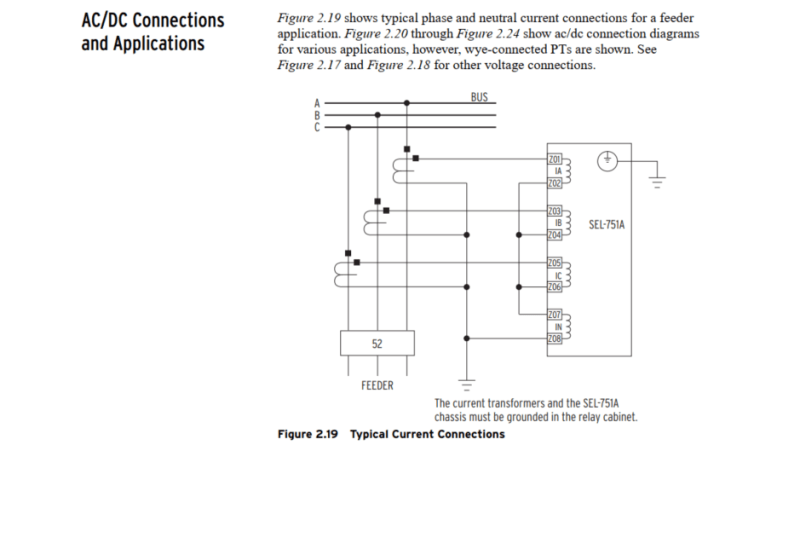
I'm trying to provide ground/neutral overcurrent setting for a land based microgrid system (The microgrid is connected to utility via Delta/Wye-grounded transformer and I have a SEL 751 relay for my protection), but I don't have much experience in ground fault protection. Therefore I would like to hear the thoughts of senior engineer in the protection field regarding my protection case.
While reading about ground fault protection, I kind of got confused with neutral overcurrent protection:
a. Neutral Overcurrent [50N]
b. Neutral Time-Overcurrent [51N]
c. Ground Overcurrent [50G]
d. Ground Time-Overcurrent [51G]
My questions are:
1.) when do we use neutral and ground overcurrent protection?
2.) do I need to use all 4 of them for my microgrid system?
3.) what are the things that I should be careful about while setting the pickup and delay settings?
Any help would be appreciated!
Thanks,

