Continue to Site

Eng-Tips is the largest engineering community on the Internet

Intelligent Work Forums for Engineering Professionals

  • Congratulations KootK on being selected by the Eng-Tips community for having the most helpful posts in the forums last week. Way to Go!

Ground Water Table in Stability Modelling

Status
Not open for further replies.

Mad Mike

Geotechnical
Sep 26, 2016
220
Hi All,

I have a site where the intention is to construct high fill embankments (50 - 70')on a hillside where there is no permanent water table. At a couple of locations on the hillside, broad, ephemeral drainage lines occur. My field testing has identified perched water tables through discrete soil horizons in the vicinity of these drainage lines and the soil profile is mostly residual dolerite clay-silt; soil class MH or A-7-5, with approximately equal proportions of clay-silt and effectively no sand or gravel.

One of the problems I'm confronted with is where to set the ground water table for my stability models. I'm looking for any reference that discusses this in detail. I have colleagues who insist that a water table will build up within my fill embankments at some point in their design life, but my feeling is that provided subsoil drains are incorporated into the valley areas, I should be able to analyze my new fill as a dry embankment.

Any help or advice would be greatly appreciated.

Best,
Mike
 
Replies continue below

Recommended for you

Mike,

I don't know of any references and I doubt you will find much in books or papers on the subject. It all comes down to local experience, how the embankment/fill is constructed, seasonal changes in groundwater conditions and precipitation, and probably many other less well understood factors.

I have worked way too many landslide projects where the cause of failure is increases in the predominant groundwater condition to not consider changes to the predominant groundwater condition. Here are some of the ways that I might deal with the conditions that you described.

1. Use a free draining fill material for all of the proposed fill. This essentially negates the placed fill from a groundwater perspective, so is a very safe option.
2. Install a fairly thick free draining fill layer between the natural soils and the proposed fill and daylight the drainage layer. Again, robust and if properly constructed, unlikely to cause a raise in groundwater levels in the natural soil. However, the fill may still saturate depending on precipitation, utility leaks, etc.
3. Model the slope (natural and fill) with elevated groundwater conditions and determine the likely FOS. If too low, flatten the slope or otherwise modify the design. Note that the target FOS should depend on how likely the conditions are to develop, this is not a one size fits all.

Good luck and let us know what you decide.

Mike Lambert
 
Mike,

Thanks so much for your quick and informative response. My bulk fills will be built up over a deep residual clay-silt profile (no significant transported soils, just a thin colluvial mantle), but for the bulk fill itself I will be using free-draining, rocky material in the lower layers at least.

Stability analyses show a relatively low f.o.s., around 1.3 when I assume a fully elevated water table in the natural profile, but no water table in the bulk fill itself. My intention was always to use rock blankets and a herringbone layout of subsoil drains across the valley bottom, but it now seems I will have to combine that with a basal geo-grid to get the desired f.o.s. (+-1.5).

It is very easy to implement the rock blanket and geo-grids over the valley bottom, so I'm happy to do so. But moving onto the sloping ground, it means having to cut an enormous basal bench on which to place the rock blanket and geo-grids, and this is the situation I'm trying to avoid. If I do opt for the conservative method suggested, which I agree with, it will lead to a significant flattening of the batters, from the current 1:2 (v:h) to 1:2.5 which means a lot of platform space is lost.

I suppose the correct option is to analyze as you've suggested, give the Client the option of either; large basal benches (cut to spoil and replace with rock grids and free draining fill material), or flatten the batters and lose some platform area.

I know that the developer and engineer will raise questions about my methodology, which is why I'm making sure I'm not being overly conservative. My founding material has a friction angle of about 24deg, and some cohesion, which I've moderated to 5kPa, so I know that 50 feet high earth embankments at 1:2 with sloping-away ground at the toe is ambitious.

Just wanted to run it past the seasoned veterans...the fill embankments in my region are just getting higher and higher as all the flat land has been developed, so I'm getting more and more of these situations.

My typical fill toe stabilization detail of late has been a basal rock grid, free-draining rock blanket of 500mm, separation fabric, and then bulk fill above. As I say, it's not prohibitive to place these over valley bottoms, but cutting huge benches for them on the slopes, and spoiling the large volumes of clay removed from those benches, creates serious drama with the Client when the volumes are put onto paper!!!

Best,
Mike
 
Hi Mike, from my understanding you are putting free draining fill on the side of a dry hill. This sounds similar to railroads and highway's in mountainous regions which I am not a specialist in but I am confident you can do some research on quite easily.

To assess the stability of the problem you first need to understand what is the stability of the existing condition. If this is a natural slope there is guidance to determine where the project area stands in relation to landslide susceptibility and if it on the brink of failure. You would then need to look at what parameters to adjust to make your project area to the brink of failure. Once you know that you can set your brink of failure to FOS 1 then work backwards to the existing condition.

In terms of pore pressures for your problem. You have mentioned that there are ephemeral drainage lines therefore you can model where the drainage line is as saturated and where they are not without. The questions then become, 1. how much time over a year is it saturated and how deep does the saturation penetrate? 2. What proportion of the slope is represented by which model and are there concentrated areas of drainage lines?
 
Mad Mike - can you post a sketch? I would think that a blanket of sand to sand and gravel - placed up against the existing slope and then the new embankment constructed and don't forget benching into the existing slope (Ohio DOT has a document on this) - the blanket of sand and gravel would act a downstream filter to a dam's clay core - very effective at drawing down and draining the existing slope - at the spots of where the localized water levels are located.

Two things I have been involved with in the past that might be useful to consider -

1. Scarborough bluffs in Toronto's East end. There are layers of fine grained material within the bluffs - but the fine grained soil slopes slightly backward from the bluff face. This creates, as you can imagine a pond of water behind that would be level with the "outlet" of the low perm layer. When erosion of the face happens, this can kick off the 'lip" and the "pond" can now drain towards the lake and, hence, slope distress (ie., failures).

2. on a project in New Brunswick a large sewer was being constructed. The original geotechnical investigation (undoubtedly "logged" by the drillers). Sand, sand, sand. Okay - open cut and control the water as the water level drops in relation to the cut. But, when they did - there was big blow-outs. One of my first jobs with a Toronto geotech firm. I found, in our forensic investigation that there were layers of fine grained material (macro) - say 3 to 4 inches thick (75-100 mm) that were actually micro layered with very fine sand, clay, etc. So, as the water level dropped, it couldn't due to the low permeability layers and then ran sideways to the cut face, undermining the sand slope - and hence progressive failures.

Bottom line - thin layers of fine, low permeability materials within what appears to be "homogeneous" materials can create havoc for groundwater - be careful and be redundant.
 
Would be interested to see a sketch as per BigH. My first thought was just free draining material between the existing slope and the embankment but in your post you've ruled that out as an option - perhaps I'm missing something obvious about the geometry.
 
Thanks Guys for all the valued responses.

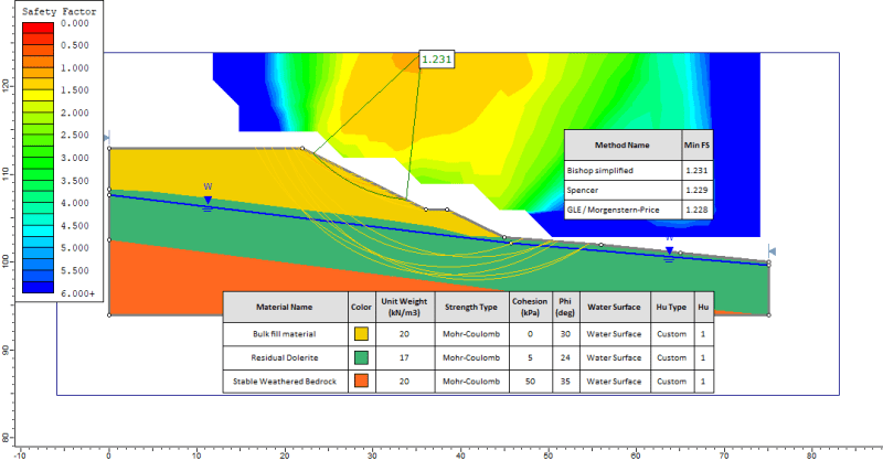
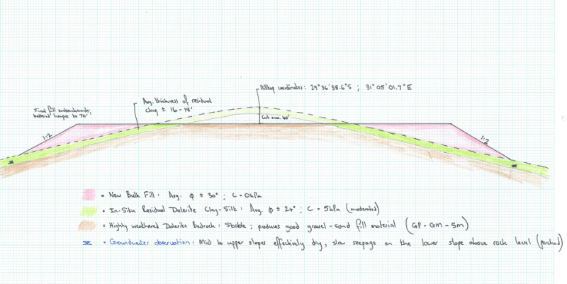
See below a sketch profile - we'll be taking the top off a natural hill, and filling out on the side-slopes. As noted by GeoEnvGuy, in general, we are putting fairly free-draining fill on the side of a dry hill. The free-draining fill material is derived from the weathered bedrock. The only groundwater seepage recorded is at depth at the toe of the slope, hence my belief that I could safely analyze my fill material as a "dry" bulk fill.

Note- I've already taken the precaution of GeoPaveTraffic and modelled the natural ground with an elevated water table. I attach also a screenshot of my stability analysis on Slide 7.

Section_B-B_1_in_2_ixygte.png


Whetstone_Phase_2_Sketch_kxyh2q.png
 
I managed to find a photo of a cutting on the adjoining site, which has almost exactly the same subsoil profile as the current site...the upper mantle of dark red-brown soil that you see in this photo is the same residual dolerite clay-silt indicated on my sketch, which will form the foundation to our high fill embankments.
 
 https://files.engineering.com/getfile.aspx?folder=bce42898-5d62-4757-ad00-99b30460ea5c&file=Whetstone_Saprolite.jpg
Status
Not open for further replies.

Part and Inventory Search

Sponsor