Eng-Tips is the largest engineering community on the Internet

Intelligent Work Forums for Engineering Professionals

Grounding in Substation Fences

Status
Not open for further replies.

AdrianDGB

Electrical
Aug 16, 2023
1
0
0
PA
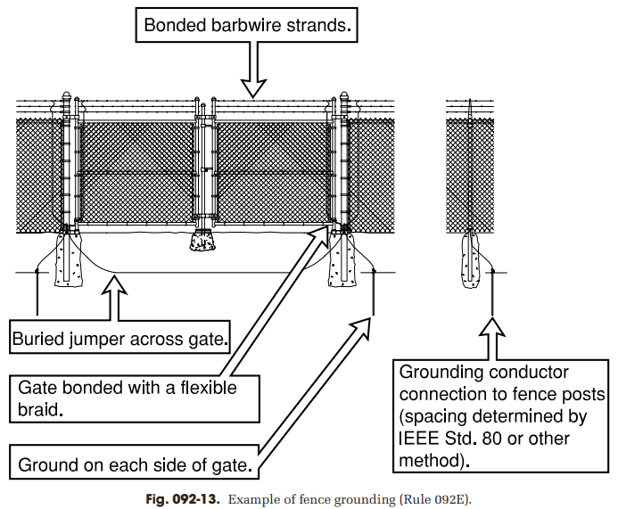
Does the grounding discharge remain confined solely to the scenario depicted in figure 092-13, where the cyclone mesh and barbed wires are connected to the ground?
100005545_ne0rvc.png


Alternatively, is it necessary to expand this approach and connect the cyclone mesh and barbed wires to the ground at various additional points? If so, at what distance intervals should these additional connections be made, both in external areas and the central area?

Furthermore, would it be appropriate to utilize a #2 gauge cable to link the cyclone mesh and barbed wires to the grounding conductor? Additionally, what type of material is recommended for the connection joints in this context?
 
Replies continue below

Recommended for you

I would also bond the barbed wire to the grounded fence post using a conductor with thermal ampacity higher than the barbed wire. For the connection from the fence post to the ground grid, I would use the same size conductor throughout the station. The cross section depends on the available fault current and expected fault duration.

The individual strands of cyclone fence run vertically, so I am doubtful that specifically bonding the individual vertical fence mesh provides any additional benefit above bonding the horizontal barbwire strands.
 
Might want to add a sign about it being copperweld to the outside of the fence. Copper thieves will still try to steal it if it looks like copper. Might not stop them (drugs are bad mkay), but maybe if they try to cut it and it is harder to cut and they see the sign they'll put 2+2 together and go away. Do like the cweld suggestion though.
 
I did the fence grounding for a major switching station many years ago.
A large copper conductor (1000 MCM) was buried alongside of the fence abour 18" deep and about 36" away.
The fence was grounded every 50 feet.
The fence was chain link.
A conductor was fed down through the fence weave and termite welded to the buried grid. (350 MCM? but memory fails.)
Said conductor was clamped to the top rail with cadmium bronze hardware.
The strands were separated and 1/3 of the conductor strands were connected to each barbed wire with Servits.
The gates were grounded in a similar manner at the pivot end, except;
The vertical conductor was terminated at the bottom rail with a cadmium bronze fitting.
A second vertical wire was fastened high on the gate and low on the supporting post and it was this conductor that was welded to the ground grid.
This station combined the 500 kV feeds from two originally and in later years more, major hydro projects.
As I recall the site was 13 acres, with additional space available for expansion.
For a smaller capacity station you may not need such large grounding conductors to control touch potentials.

--------------------
Ohm's law
Not just a good idea;
It's the LAW!
 
and the grounding grid extends outwards as required to accommodate the swing of the gate.

-----*****-----
So strange to see the singularity approaching while the entire planet is rapidly turning into a hellscape. -John Coates

-Dik
 
Ground Potential Rise tends to NOT rise past the perimeter grid.
There may be exceptions.

--------------------
Ohm's law
Not just a good idea;
It's the LAW!
 
Status
Not open for further replies.
Back
Top