Continue to Site

Eng-Tips is the largest engineering community on the Internet

Intelligent Work Forums for Engineering Professionals

  • Congratulations KootK on being selected by the Eng-Tips community for having the most helpful posts in the forums last week. Way to Go!

Gusset Connection Eccentricity Problem 9

Status
Not open for further replies.

dik

Structural
Apr 13, 2001
25,675
I have a new project to design bracing for an existing building. The force in the bracing is Cf = Tf = 103K... big forces!

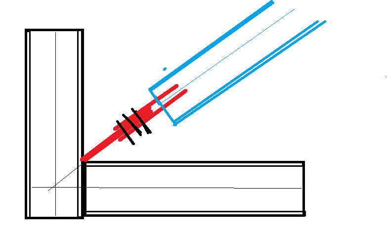
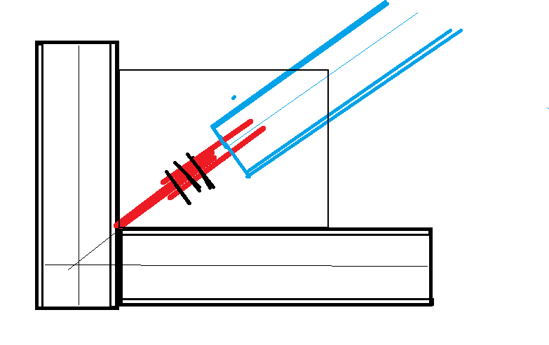
The problem is that the gusset will be secured at the centroid of the resisting beams and columns because there is an existing masonry wall located to the centerline of the connection. The EOR want me to design the connection for an HSS 10x4x0.5 (located at the face of the wall), welding the HSS to the face of the gusset, creating an eccentricity of 2" (from the HSS) + half the thickness of the gusset.

I've designed it using elastic combined stresses, based on a Whitmore width for compression. If it weren't for the compressive load, I'd have used the plastic section. I'm looking for some comments how others would design this for the eccentricity. I've suggested going to plate that is roughly 1"x12", in lieu of the HSS, to minimise eccentricity or possibly using the existing masonry wall for lateral forces.

Rather than think climate change and the corona virus as science, think of it as the wrath of God. Do you feel any better?

-Dik
 
Replies continue below

Recommended for you

The forces at each end would cancel? What is the stress condition at the junction of the gusset and the HSS? Wouldn't you have to transfer part of the moment load from the centroid of the HSS to the gusset of the or just strictly by shear? Wouldn't the moment be at least the shear x half the thickness of the gusset, then?

Clipboard01_dx7a3t.jpg


That is the Whitmore wide for compression?

Rather than think climate change and the corona virus as science, think of it as the wrath of God. Do you feel any better?

-Dik
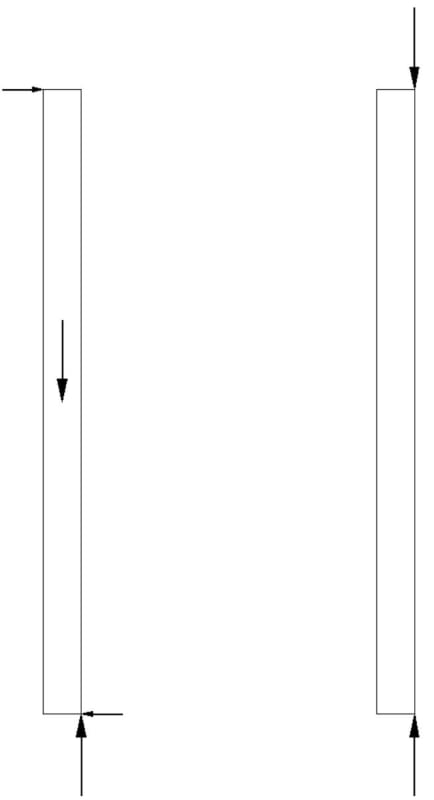
 
The model on the right reflects how your brace will be loaded, correct? If so, then yes, there is no shear in the brace, and no out-of-plane shear will be delivered to the gussets at the ends.

You can design the gusset for weak axis moment, but you don't need to to satisfy equilibrium. If you choose to design the brace for the entire moment and the gusset for axial force only, you would technically have a moment at the brace-gusset interface equal to P*(tg/2), but that's often neglected in the weld design.

Whitmore width is 30 degrees if you need the gusset to behave elastically at design loading, but if you can tolerate some yielding it can be as high as 45 degrees. See this paper: Link.
 
Deker said:
You can design the gusset for weak axis moment, but you don't need to to satisfy equilibrium.

Maybe I'm misunderstanding something, but I would fundamentally disagree that you don't need to satisfy equilibrium. Looking at a free-body diagram of the gusset, you have axial loads which are offset, therefore, to satisfy equilibrium, there must be some additional forces acting on the gusset which must be taken into account in the design. Looking at dik's last sketch (the one on the right), it might be case where the eccentricity is only 1/2 the gusset thickness and would be very manageable.

Deker said:
If you choose to design the brace for the entire moment and the gusset for axial force only, you would technically have a moment at the brace-gusset interface equal to P*(tg/2), but that's often neglected in the weld design.

This is a tough one. Often in connection design you need to make some assumptions about how/where eccentricity is resolved. If the assumption does not impact the connection design in a significant way I'll often design for the eccentricity being resolved on either side of the connection. In this case, the brace is offset from the centerline of the beam/column - this eccentricity needs to be resolved either in the brace (weak-axis bending), in the beam/column (torsion), or by additional external bracing. Assuming no additional external braces, that eccentricity will be resolved by both the brace and the beam/column and this split will be based on the relative stiffness of the entire system. As noted above, sometimes I'll run two connection checks assuming each side takes 100% and see where that lands me.

In this case, I feel like the EOR is putting dik in a tough spot as a connection designer and I would be sending an RFI asking specifically about how this connection eccentricity is resolved. If the EOR designed this brace properly, they should already be aware of how this connection eccentricity impacts the new and existing members.

 
Deker... good link, give me something to read.


That's what I'll use. Because the loads are compression and very high, I'll use the 30deg slope; I'm not keen on plastic compression... if tension, no problem. This has been a real 'eye opener'; I've never designed gussets for such a high eccentricity, and my approach was conservatively flawed.


My SMath program can automatically include for this. I have to revise my program to design from (b[sub]HSS[/sub] + t[sub]g[/sub])/2 to t[sub]g[/sub]/2. It's an easy fix... I'll do that tomorrow... I don't design my welds for different directions of load... and include for shear lag...

I'll post it when it's updated...

Rather than think climate change and the corona virus as science, think of it as the wrath of God. Do you feel any better?

-Dik
 
Didn't say that equilibrium doesn't need to be satisfied, but I probably worded that poorly. Should have written "You can design the gusset for weak axis moment, but you don't need to in order to satisfy equilibrium." If you design the brace/gusset weld for P*(tg/2), the gusset does not need to resist moment to satisfy equilibrium.

The designer can choose to proportion the total eccentric moment in any way that satisfies equilibrium provided there is sufficient ductility to allow force redistribution. Since the weak-axis stiffness of the brace will be so much larger than that of the gusset, a solution that proportions more of the eccentric moment to the brace is going to better reflect the elastic force distribution. I'm certainly not opposed to designing the gusset to resist an eccentricity of half the plate thickness. Just wanted to remind Dik that it's not strictly necessary provided the moment can be taken by the brace. I do recognize that an elastic force distribution will induce some moment in the gusset, which is why I suggested to detail the gusset to beam/column connections to develop the capacity of the plate. This will allow the plate to shed it's moment back to the brace to satisfy the force distribution assumed in design.

 
Thanks Deker... understood and I'm comfortable to proceed based on the reduced eccentricity. As always, you gentlemen (I use the term for male and female, I think it's better than 'you guys') have been a lot of help.

Rather than think climate change and the corona virus as science, think of it as the wrath of God. Do you feel any better?

-Dik
 
Deker (or anybody else), would you mind indulging me in further explaining this.

Deker said:
"You can design the gusset for weak axis moment, but you don't need to in order to satisfy equilibrium." If you design the brace/gusset weld for P*(tg/2), the gusset does not need to resist moment to satisfy equilibrium.

It doesn't make sense to me at them moment. But there seems to be a tiny piece of the puzzle regarding the eccentricity that I'm not quite getting. I'll be pondering this myself, because there seems to me an important concept I don't properly grasp here. But anybody who wants to help me along the way would be appreciated.
 
The eccentricity between the line of action at the gusset and line of action at the brace (gusset thickness / 2 + brace width / 2) creates a free moment that has to be resisted somewhere in order to satisfy equilibrium. The elastic force distribution will proportion this moment to each element in the system based on its relative stiffness. If you can allow (i.e. detail) the system go plastic, you can choose any force distribution that satisfies equilibrium based on the lower bound theorem, so you are not bound by the elastic solution.
 
Deker, thanks for the follow up. I think we're on the same page here. I agree that the brace would likely resolve majority of the eccentricity.

human909, if the brace is able to resist some bending, in terms of both strength and stiffness, then the gusset plate sees direct shear coming from the welds to the HSS...which means the plate only sees an eccentricity of half the plate thickness. If in another case (this is purely hypothetical), the opposite end of the brace could not transmit any shear (roller in two-directions), the end of the brace in question could not carry any bending moment...forcing the beam and column to resist 100% of the eccentricity. This would put significantly more bending in the gusset.
 
Thanks for the explanation Deker and Canpro. I think I need to ponder this a little further and do a little work myself. It hasn't quite clicked yet but I need to start drawing some load path diagrams and make the connection. I'm sure once I do they it will be a 'of course' silly me moment. [smarty]
 
I would check that neither the brace nor the gusset is too flexible. Treating the gusset as a pin means it follows the slope at the end of the brace caused by the uniform moment --> additional eccentricity. Then, if the gusset is long as Dik suggested, you may get a p-delta increase there as well if too flexible.
 
P-delta... another thing to add to SMath program... I thought it was way too stiff... maybe not.

So strange to see the singularity approaching while the entire planet is rapidly turning into a hellscape. -John Coates

-Dik
 
May be worrying about nothing, but not sure exactly what 'several inches' means, or how much thinner the EOR wants the plate. If it's only just working with linear calcs, it may not with non-linear.
 
The EOR wants it thin so the gusset doesn't transfer moment to the connection. The thicker the gusset, the greater moment is transferred to the connection. I've seen gussets buckle under compressive loadings. He doesn't want to take 'ownership' of the gusset and simply give me a thickness to connect to. That was my original solution when I came up with a conservative thickness. He wants me to design the gusset. He's not happy about me stipulating that the strength of the existing beam-column combination has not been checked. Just cannot seem to 'win' some days. [ponder]

So strange to see the singularity approaching while the entire planet is rapidly turning into a hellscape. -John Coates

-Dik
 
Sounds like the EOR wants you to design a perfect hinge at a point that in not eccentric to the beam/column. That is a tall ask.

Something like this could work if you can keep the boltline non eccentric to the beam column, but would be quite an unusual approach to connect things.
temp_gmjbxl.png
 
Something like... his concern is the moment in the other direction:

temp_gmjbxl_fmsqog.png


So strange to see the singularity approaching while the entire planet is rapidly turning into a hellscape. -John Coates

-Dik
 
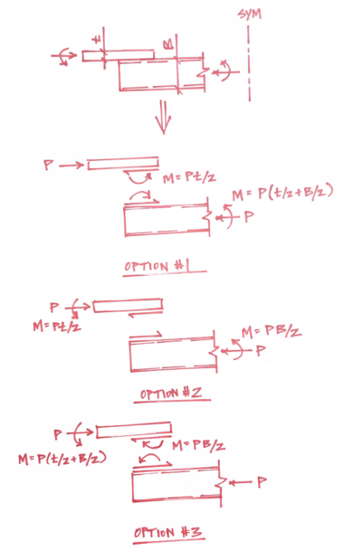
human909: Check out the FBDs below and see if it clicks. If there's sufficient ductility in the system to allow force redistribution, any of these options are valid. The elastic solution would likely fall between options 1 and 2, so either of these options could produce an efficient design. Given the proportions discussed in this thread, option 3 would be irrational (though still valid) and would result in a very inefficient design.

Untitled_iikmsb.png
 
Deker those are some sexy FBDs. Thanks for that.
 
Thanks Deker for those drawings, above an beyond in your assistance. It has now 'clicked' for me.
 
Status
Not open for further replies.

Part and Inventory Search

Sponsor