Continue to Site

Eng-Tips is the largest engineering community on the Internet

Intelligent Work Forums for Engineering Professionals

  • Congratulations KootK on being selected by the Eng-Tips community for having the most helpful posts in the forums last week. Way to Go!

Guyed Distribution timber poles as strut/column 2

Status
Not open for further replies.

designdraft

Electrical
Jan 17, 2004
20
I find many statements like this about stayed/guyed timber poles:
[highlight #FCE94F]Because directly embedded wood poles are generally very flexible, it has traditionally been assumed that all the transverse load is picked up by the guys,
leaving no moment at the base of the pole. With this "column" analysis, the wood pole acts as pure compression member which is only checked against buckling.[/highlight] (Design of Guyed Electrical Transmission Structures, ASCE no 91)
but I have never found any actual justification for it. Does anyone have any proof this is a valid approach other than "it works" or "it's always been done that way"?
Thanks!
 
Replies continue below

Recommended for you

As they say, stiffness attracts load. The tensile modulus of the guy cable and compression modulus of the pole are much greater than the flextural modulus of the pole. The cable will snap before the pole bends enough to pick-up much lateral load.

Another way to look at it is that the system still works even if you put a hinge under the pole.
 
Is it enougn proof to observe line workers contructing an unguyed pole to guyed pole? The unguyed pole moves quite a lot as the workers move around whereas the guyed pole has little movement.

Or if you are instead looking theoretical analysis, PLS-CADD or other finite element software analysis tools can show the "exact" very small portion of transverse load the pole picks up. Keep in mind that the workmanship of raking the pole as part of guy installation plays a large role in determining which loading conditions result in the pole being vertical.
 
Thank you for your responses. I'll do more thinking sbout this and see where I get.
 
More folks are likely to respond when you place information directly in your post. You can now embed images directly in your post using the image icon. Requesting folks to download a file puts a both a time burden every forum user and it is an undesireable security practice.
 
This is what I have got so far, any comments would be appreciated.

A pole can be modelled in one of two ways—being free to move at the base (like a hinge) or being fixed at the base.
Hinged Pole
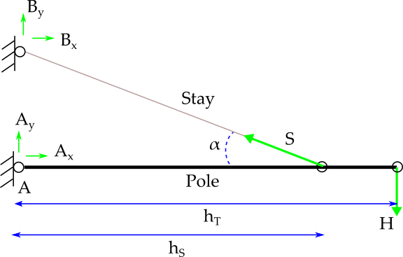
Figure 1 is a free body diagram of a pole with one stay and a tipload (equivalent load applied at pole tip). The pole is modelled as hinged at ground level.
free_body_pole_hinged_stay_hqjdj2.png

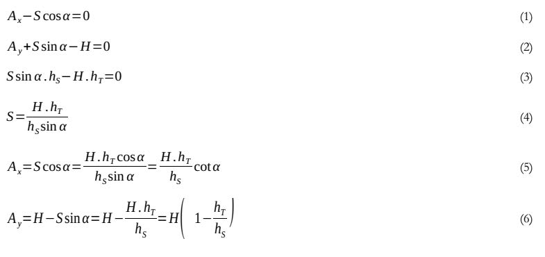
The system is in static equilibrium so the equations that apply are
eqn1_eckhvc.jpg


Equation 3, the bending moment at the pole base, equals zero by definition; the pole is free to rotate about the base. All horizontal resistance is provided by the stay and equation 4 shows that the tipload H is transferred in full on to the stay, increased by factors due to attachment heights and the angle of the stay.
The compressive load in the pole is A[sub]x[/sub] (eqn 5) and tension in the stay wire is given by equation 4.
These observations show the quotation above would be valid if the pole is modelled as hinged.
Fixed Pole
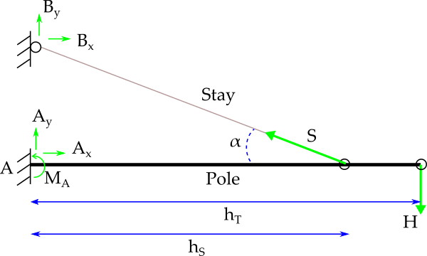
free_body_pole_fixed_stay2_ekh9ix.png

Similar to figure 1, figure 2 is the free body diagram for a pole modelled as fixed at the base. The load is distributed between pole and stay according to the ratios
eqn2_kqhwyx.jpg

A cross-sectional area of stay
E modulus of elasticity of stay
L length of stay wire
β angle between ground and stay = 90 - α
E[sub]P[/sub] modulus of elasticity of pole
d[sub]g[/sub] groundline diameter of pole
d[sub]a[/sub] tip diameter of pole
h pole height above ground

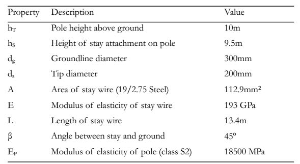
Looking at some realistic values:
table1_qyikw5.jpg

K[sub]S[/sub] = 8.13 x 10[sup]5[/sup] N/m = 813 kN/m
K[sub]P[/sub] = 1.47 x 10[sup]4[/sup] N/m = 14.7 kN/m
Equation 7 shows that the stay carries 813 / (813+14.7) = 98% of the transverse load. In reality, because of ground movement and creep, the stay could be considered as carrying all the load. K[sub]P[/sub] is directly proportional to E[sub]P[/sub] and K[sub]S[/sub] is directly proportional to E so even for a combination of the least flexible timber and the weakest cable the stay will still carry the majority of the transverse load.
Our brief exercise shows the quotation above is also valid if the pole is modelled as fixed at the base.
 
Yes, your example is matches nicely with why ASCE no 91 excludes transverse loading on guyed poles.
 
The second figure is statically indeterminate, bringing in stiffness and elasticity. I prefer the simpler equations from statics. I also question the validity of stiffness and elasticity over the life of an installation.
The assumption the pole is fixed at the ground line is also a problem, since even compacted soil can move.
 
designdraft said:
Does anyone have any proof this is a valid approach other than "it works" or "it's always been done that way"?

This is a valid approach because it is a conservative approach, both for determining the required strength of the pole as well as the guy wire. By assuming that the base of the pole is pinned, you're forcing all of the horizontal load into the guy wire (i.e. maximizing the required strength). In turn, you are maximizing the vertical component of the force in the guy which is resisted by the pole acting as a column. The buckling strength of the column is determined by kl/r, where k is the effective length value, l is the length, and r is the radius of gyration. A column that is pin-pin connected has k=1 while a pin-fix column has a k=0.7. By assuming that the column is pinned at the bottom you are increasing the kl/r value and by default decreasing the allowable buckling strength of the column.
 
But depending on how much moment is in the pole you may not be conservative by assuming pinned. It is a beam column in reality.
 
Kwan (Aerospace) said:
But depending on how much moment is in the pole you may not be conservative by assuming pinned.
As Compositepro mentioned at the beginning of this thread, "stiffness attracts load". A wood pole is flexible enough that it would have to deflect much further than the guy wire would allow before any moment at the base of the pole becomes an issue. So, for this system, it will always be conservative to assume a pinned connection at the base.
 
Of course the relative stiffness is the key! But I'm just saying that the pole can be stiff enough that choosing to just assume pinned (edit) may not be conservative. I'm just pointing out that this is a beam column and one must understand this relative stiffness to make sure the analysis is conservative.
 
Relative to what? Can you give an example of a guyed pole where a guy designed to fully compensate for conductor loading is not conservative?
 
Status
Not open for further replies.

Part and Inventory Search

Sponsor