Continue to Site

Eng-Tips is the largest engineering community on the Internet

Intelligent Work Forums for Engineering Professionals

  • Congratulations MintJulep on being selected by the Eng-Tips community for having the most helpful posts in the forums last week. Way to Go!

Hack cheap synchronous motor for single direction? 1

Status
Not open for further replies.

mkeveney

Computer
Sep 2, 2014
5
Hi All,

I'm new here; please direct me if this has already been answered.

I want to use one of these cheap synchronous motors ( in a hobby project, but I need it to turn in a predictable direction. I understand that this style motor (with two leads only) might start in either direction, depending on where the rotor comes to rest.

Is there a way to modify the motor so it always starts in one direction? I've seen vague references to a capacitor in a few places, but not enough detail.

Thanks in advance.

-Matt
 
Replies continue below

Recommended for you

That looks like a shaded pole clock or timer motor. If so, it will be a shaded pole motor and will always run in the same direction.
Reversing such a motor requires the motor to be disassembled and reassembled with the stator upside down. This is often possible with small shaded pole fan motors but not with all shaded pole motors.
Most shaded pole motors are asynchronous induction motors that slip a small amount below synchronous speed.
The shaded pole motors used in clock and timer motors have steel buttons set into the rotor. These buttons "cog" at synchronous speed.

Bill
--------------------
"Why not the best?"
Jimmy Carter
 
Does it "cog"? If it does, then it is a synchronuous motor. If it doesn't it is probably a shaded pole motor as Bill says.

If it is, and these motors are known to start in either direction (a beautiful illustration of the fact that a single phase sinewave actually are two opposing sinewaves) and if there are two wires, as you say, there's not much to do without dismantling it and see if there are more than one winding.

If there's just one winding - there's not much to be done electrically.

If there are two or more windings - you can create a preferred direction by adding a capacitor in series with one of the windings.

That's about all that can be done.


If you read the site rules, you will notice that EngTips is about professional engineering. Sometimes, the custodians can be fussy about that. But I hope that your mentioning of a "hobby project" doesn't mean that this thread disappears. If it does, you now know why.


Gunnar Englund
--------------------------------------
Half full - Half empty? I don't mind. It's what in it that counts.
 
Are you referring to the sample motor Gunnar? I can't remember seeing a motor that starts in a random direction. A single phase motor needs two electrically dissimilar windings to generate the initial starting torque or it usually doesn't turn at all. Think "broken starting switch".(Yes, the addition of a capacitor will make two identical windings "electrically dissimilar" for starting purposes.)
I know that you know that even better than I do, friend, but your phrasing is a little confusing.
Note that in a shaded pole motor, the second winding is a single loop of fairly heavy copper around part of each pole.
By electrically dissimilar we mean different X/R or Reactance/Resistance ratios so that the current peaks occur at different times in the cycle. This may be achieved with a capacitor or by making one winding of a higher resistance than the other. Both methods work but the capacitor works better. (More starting torque.)

Bill
--------------------
"Why not the best?"
Jimmy Carter
 
I was thinking the kind of motor that you can find in citrus presses. They start in either direction. You can use them instead of flipping a coin - provided, of course, that you happen to have such a press instead of a coin. And a suitable AC outlet nearby. [bigsmile]

You are right that the shaded pole motor actually has more than two windings. But I don't think that it is practical to add a capacitor to the shorting ring. And that wouldn't change things for the better. It would probably rend the motor useless.

Have a look at the Philips type HR 2771 and similar presses (that is what I use to flip coins).

Gunnar Englund
--------------------------------------
Half full - Half empty? I don't mind. It's what in it that counts.
 
...more than on winding...

Gunnar Englund
--------------------------------------
Half full - Half empty? I don't mind. It's what in it that counts.
 
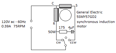
No way to know what that motor is from that photo, but this might help.

GE_Motor.gif


"Will work for (the memory of) salami"
 
The OP says that the motor starts in either direction.

The only motor type I know of, that does that, is the one that Philips uses in their citrus press. I checked the voltage on the plug when I turned the press by hand. The peak voltage was a little more than 1000 V. And there is a distinct cogging. So, I guess that there's a PM and dents in the rotor and stator, like a stepper motor - but with just one winding. They can also produce nasty voltages when shaft is turned.

And then, with one winding,it is not possible to do anything with a capacitor.

mkeveney: Why have you chosen a motor that you know practically nothing about? It is like finding a steering-wheel and then build a boat that fits it...


Gunnar Englund
--------------------------------------
Half full - Half empty? I don't mind. It's what in it that counts.
 
Thanks for all the suggestions folks. I think I'm going to have to get one and do some experimenting. Maybe I'll take it apart and take some photos.

Skogsgurra:
>The OP says that the motor starts in either direction.
> The only motor type I know of, that does that, is the one that Philips uses in their citrus press.

I gleaned from an ancient post somewhere that these motors are used to drive the rotating plates in microwave ovens. Those plates do seem to 'randomly' start in either direction, so I'm inclined to believe it.

>mkeveney: Why have you chosen a motor that you know practically nothing about? It is like finding a steering-wheel and then build a boat that fits it...

I guess I'm trying to design around an available power-plant; I didn't think that was so unusual.

What I do know is that the torque is adequate and it's cheap and easy to find in lots of gear ratios. Search 'synchronous motor AC (110,120)' on eBay and you'll see lots of them for about $7.00. I'm going to need a handful of these, so cost is a consideration. If you know of a source for a similar, synchronous motor that's guaranteed to run in one direction (or better yet, is reversible), that would be great!

jraef: Thanks so much for the circuit diagram. I'll see if that can be applied.

I thought that maybe because it seemed so common, perhaps, one of you would have some experience with this _particular_ type of motor. I asked here because this seems to be an active forum with lots of helpful contributors. I certainly hope I haven't offended with my 'hobby' question.

Thanks again!

-Matt
 
Some of these motors have a crude sprag clutch or ratchet which stalls the motor if it tries to go the 'wrong' direction. There's enough mechanical spring in the clutch to cause it to rebound slightly and start rotating in the 'right' direction.

 
> Some of these motors have a crude sprag clutch or ratchet...

Interesting! I'll look for that when I take it apart.

-Matt
 
Skogsgurra:
> Does it "cog"? If it does, then it is a synchronuous motor.

These are always advertised as 'synchronous' motors, so I presume that's what they are...

but what do you mean by 'cog'? How could I test that?

-Matt
 
As you rotate the shaft it will have a pronounced preference to rest in certain regularly-spaced positions and not in the intermediate positions. This is due to the design of the magnetic components in the stator and rotor. It will be hard to feel this through a gearbox, but quite easy if you have the motor alone.
 
Sorry, was AFKB for a while. But Scotty answered already. And I learned something new. That ratchet is an obvious solution - once you think about it.

Gunnar Englund
--------------------------------------
Half full - Half empty? I don't mind. It's what in it that counts.
 
The field of most single phase induction motors or single phase synchronous motors does not provide a torque to a stationery rotor. Once the rotor has started turning the field will provide torque as the magnetic field of the stator interacts with the magnetic field of the rotor due to the lagging rotor current due to the inductive reactance of the rotor.
There are a number of techniques to develop a phase shift in a starting winding so as to develop starting torque.
Designing a small motor that will reliably start in random directions may be a challenge. That said, such motors do exist.
Clock and timer motors are built with small synchronous motors and gear trains with different ratios and they ALWAYS start in the same direction.
Look for a clock or timer motor. There are quite a few that look very similar to the picture in your link.

Bill
--------------------
"Why not the best?"
Jimmy Carter
 
I knew if I waited long enough somebody would explain what 'cogging' is so I wouldn't have to reveal my ignorance of the term...oops, I guess I just did... [bigsmile]

Our residential microwave turntable randomly rotates either way from one start to the next, as does our barbecue rotisserie motor. I assumed this was just because this type of motor would be less expensive to manufacture...

I don't really care in the first case, but in the second I wish it always started counter-clockwise when viewed from the 'spindle insertion end' since, for optimum basting, the side of the meat on the spit facing the chef/cook should always rise [the drive motor is on the RH side of the BBQ]. As a result, multiple starts may be needed to get the unit spinning in the correct direction.

ScottyUK said:
Some of these motors have a crude sprag clutch or ratchet which stalls the motor if it tries to go the 'wrong' direction. There's enough mechanical spring in the clutch to cause it to rebound slightly and start rotating in the 'right' direction.

Interestingly enough, the rotisserie motor does have this feature, the idea being that if some protruding portion of the meat sustains mechanical interference with some internal portion of the BBQ, the unit will stall and eventually reverse its direction of rotation, minimizing the chances of the meat catching fire.

CR

"As iron sharpens iron, so one person sharpens another." [Proverbs 27:17, NIV]
 
Can anyone explain how the random start direction motors are constructed?

Bill
--------------------
"Why not the best?"
Jimmy Carter
 
Another example of a synchronous motor is in aquarium "power heads"..
as shown in this image (red circle) there is a mechanical rubber bumper to "bounce" the motor back into the right direction if it does start backwards..
The prop on the shaft also has some axial play so the backwards prop will pull it into the bumper while a properly running direction pushes the prop the other way thus avoiding the bumper.
 
I got one of the TYC-50 motors I was talking about and took it apart. I thought I'd post a description and some photos for posterity.

The motor cost a bit less than $10.00 on eBay, including shipping. It was delivered from China to California in about a week. It's housed in a stamped sheet-metal can of galvanized steel, or maybe plated brass; I'm not sure. It's about 50mm dia x 20mm long, with an offset shaft about 7mm dia (1/4" maybe) by 12mm long.

I connected it to a lamp cord and plugged it in. It worked just as advertised, turning precisely 1 rpm (we have 60-cycle, 110V mains in the USA), and would indeed start randomly in either direction. The motor is quite silent though I could feel it vibrating in my hands, so it might make a noticeable hum if mounted in a wooden case, say.

I did not measure torque, but I could not stall the motor with my fingers. (There's a transverse hole in the shaft through which I put a nail to get a good grip on the shaft.)

The output side of the motor is a sheet metal stamping retained by four crimped tabs in the housing. I was able to pry them back with needle nosed pliers.

This revealed a five-stage gearbox, with a mixture of brass and plastic gears. The gears run on fixed axles mounted to another sheet-metal piece at about half the depth of the can. The other ends of the shafts are supported by holes in the cover piece.

The rotor is a 'tubular' permanent ceramic magnet with a plastic output gear pressed or perhaps cemented into the center. The rotor lies centrally, in the lower half of the motor, below the central sheet, with its output pinion protruding into the upper, gearbox half. It rides on a full-length axle fastened to the can. The other end of this axle is supported by a hole in the cover piece like the rest.

The central sheet piece is just friction-fit into the case, and was easily removed after bending one of the edges down slightly to get a grip with the pliers. This revealed the coil. It's a single coil, wound axially, about a plastic bobbin about 6mm wide (inside dimension). The bobbin was separated from the central sheet piece by a thin plastic 'washer' perhaps to give it a snug fit.

The coil is wound from the finest wire I've ever seen, and broke from the power leads the instant I handled it. I have no means of measuring the gauge. It's wound on the bobbin for a depth of only about 3mm, though the bobbin looks like it would accommodate about 10mm... except that the power leads ends also fit in this space, so call it 7mm max.

Since there's just a single winding, I think I can conclude that adding a capacitor will not force it to turn in a predictable direction.

Before disassembling, I attempted to force the motor to start in a given direction by manually applying pressure to the output shaft before plugging it in; thus simulating the ratchet idea mentioned by xxx. This was ineffective, probably because the gear train isolates the rotor from this pressure. I suspect that the ratchet must be applied to the rotor shaft for this to work.

Interestingly, the rotor pinion is molded with two small 'wings' on the flange that extend maybe 1.5mm past the radius of the pinion. Perhaps the ratchet variants of this motor have a pawl that bears on these wings. There is an additional axle hole on the central divider piece that might support such a pawl, but no matching hole in the output side sheet.

Or, it might be that the plastic 'washer' I mentioned is taking the place of this optional ratchet mechanism. It's positioned at about the same depth as the pinion 'wings.'

At present I have no way to make an experimental pawl to test this, but I remain intrigued by the idea.

But, for now I think my answer is: no, this motor _cannot_ conveniently be 'hacked' to turn in a predicable direction. Too bad! I really wanted this nice cheap motor to work. I guess I'll keep looking for an alternative.

I hope this information is useful to someone. If you have any further information on this style motor, I'd be most grateful.

-Matt


Very nice work, Matt!

I liked the text and the pictures. Yes, I am a total nerd in some resoects.

LPS for you.


Gunnar Englund
--------------------------------------
Half full - Half empty? I don't mind. It's what in it that counts.
 
Status
Not open for further replies.

Part and Inventory Search

Sponsor