I got one of the TYC-50 motors I was talking about and took it apart. I thought I'd post a description and some photos for posterity.
The motor cost a bit less than $10.00 on eBay, including shipping. It was delivered from China to California in about a week. It's housed in a stamped sheet-metal can of galvanized steel, or maybe plated brass; I'm not sure. It's about 50mm dia x 20mm long, with an offset shaft about 7mm dia (1/4" maybe) by 12mm long.
I connected it to a lamp cord and plugged it in. It worked just as advertised, turning precisely 1 rpm (we have 60-cycle, 110V mains in the USA), and would indeed start randomly in either direction. The motor is quite silent though I could feel it vibrating in my hands, so it might make a noticeable hum if mounted in a wooden case, say.
I did not measure torque, but I could not stall the motor with my fingers. (There's a transverse hole in the shaft through which I put a nail to get a good grip on the shaft.)
The output side of the motor is a sheet metal stamping retained by four crimped tabs in the housing. I was able to pry them back with needle nosed pliers.
This revealed a five-stage gearbox, with a mixture of brass and plastic gears. The gears run on fixed axles mounted to another sheet-metal piece at about half the depth of the can. The other ends of the shafts are supported by holes in the cover piece.
The rotor is a 'tubular' permanent ceramic magnet with a plastic output gear pressed or perhaps cemented into the center. The rotor lies centrally, in the lower half of the motor, below the central sheet, with its output pinion protruding into the upper, gearbox half. It rides on a full-length axle fastened to the can. The other end of this axle is supported by a hole in the cover piece like the rest.
The central sheet piece is just friction-fit into the case, and was easily removed after bending one of the edges down slightly to get a grip with the pliers. This revealed the coil. It's a single coil, wound axially, about a plastic bobbin about 6mm wide (inside dimension). The bobbin was separated from the central sheet piece by a thin plastic 'washer' perhaps to give it a snug fit.
The coil is wound from the finest wire I've ever seen, and broke from the power leads the instant I handled it. I have no means of measuring the gauge. It's wound on the bobbin for a depth of only about 3mm, though the bobbin looks like it would accommodate about 10mm... except that the power leads ends also fit in this space, so call it 7mm max.
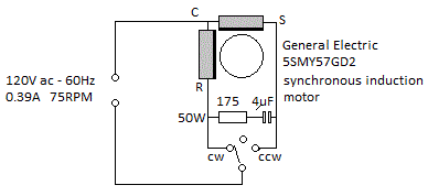
Since there's just a single winding, I think I can conclude that adding a capacitor will not force it to turn in a predictable direction.
Before disassembling, I attempted to force the motor to start in a given direction by manually applying pressure to the output shaft before plugging it in; thus simulating the ratchet idea mentioned by xxx. This was ineffective, probably because the gear train isolates the rotor from this pressure. I suspect that the ratchet must be applied to the rotor shaft for this to work.
Interestingly, the rotor pinion is molded with two small 'wings' on the flange that extend maybe 1.5mm past the radius of the pinion. Perhaps the ratchet variants of this motor have a pawl that bears on these wings. There is an additional axle hole on the central divider piece that might support such a pawl, but no matching hole in the output side sheet.
Or, it might be that the plastic 'washer' I mentioned is taking the place of this optional ratchet mechanism. It's positioned at about the same depth as the pinion 'wings.'
At present I have no way to make an experimental pawl to test this, but I remain intrigued by the idea.
But, for now I think my answer is: no, this motor _cannot_ conveniently be 'hacked' to turn in a predicable direction. Too bad! I really wanted this nice cheap motor to work. I guess I'll keep looking for an alternative.
I hope this information is useful to someone. If you have any further information on this style motor, I'd be most grateful.
-Matt

![[bigsmile] [bigsmile] [bigsmile]](/data/assets/smilies/bigsmile.gif)
