Eng-Tips is the largest engineering community on the Internet

Intelligent Work Forums for Engineering Professionals

  • Congratulations waross on being selected by the Tek-Tips community for having the most helpful posts in the forums last week. Way to Go!

HAIR PIN well below Anchor Rods (At column/ pedestal base) 1

Status
Not open for further replies.

palk7 EIT

Structural
May 12, 2020
142
US
Hi,

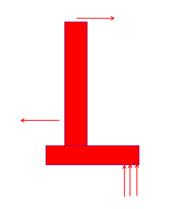
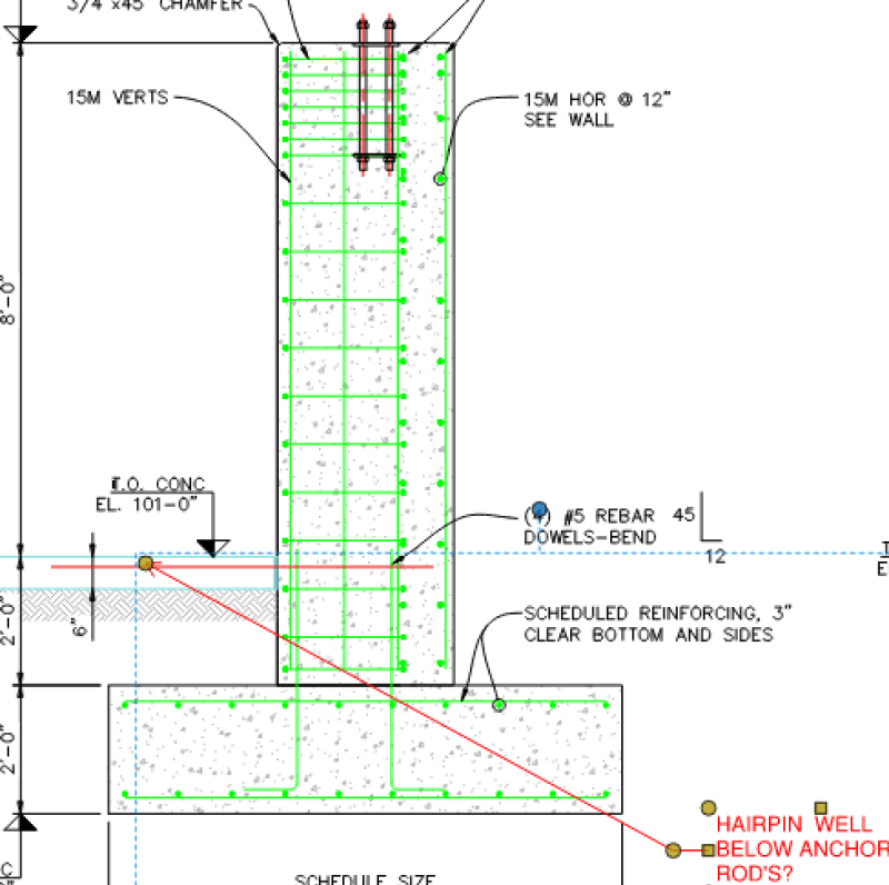
I have a situation where in order to take out the lateral thrust onto the S.O.G and not design huge footings for that moment (Horiz. Load* Height from top of footing to U/S of base plate), attached the snip below for reference...... If I place my hair pins at the bottom of my col. and connect the column to S.O.G, can I not worry about the Lateral thrust?, its a PEB portal frame. Thank you! for responses

Hp_dpfq0w.png
 
Replies continue below

Recommended for you

At the other end there will be another column in the same line and it will to0 have the same situation where the anchor plate is at top and S.O.G is 8 feet below
 
Hairpins don't have a lot of capacity typically, usually less than 10 kips for large bays. Where phamENG is going here is you have to develop the hairpins into the slab and if the columns are spaced too closely you get less capacity as the zones intersect. You would also need a reinforced slab that you are developing into that can transfer across the building, typically you would have construction joints that would need continuous rebar across to continue the load path.

Now to your problem - what kind of force do you have on this pedestal? You mention portal frame, is this the main frame lines or an actual portal (moment) frame for lateral stability, typically along the exterior of the building? Because you are not able to create a fixed base connection at the top of the pedestal, the way I see this is you have a couple developing to form a cantilever pedestal and therefore will have a horizontal reaction at the hairpins and a horizontal reaction at the foundation below that you will need to design sliding for. With what you have I would believe a moment foundation would probably provide the best design based on the given information, espeically being that the pedestal is 8' tall and the eccentricity from hairpins to footing is approximately 2' therefore you are looking at horizontal reactions of about 4x the actual loading put into the top of pedestal to handle the moment.
 
Hi Aesur, thank you for in-depth detail!

To Answer your questions:-

The horizontal load max is 14.6Kips
Its an actual portal frame for lateral stability typical pre-eng build.
Foundation designed it for sliding for the horizontal reaction, worked out.
Designed the pedestal for that lever arm distance of 8 feet (from top of pedestal to the S.O.G where the pin is, the horiz. load)

The danger item is, actually the footing is going to be another 9 feet below cuz of the frost depth, so its not at 2 feet down from the slab, that's why I worry about doing it as a moment footing cuz the bearing pressure was crazy.
 

- (9 ft + footing ht ) would be around 11 ft.. seems too high ..suggest you to check the frost depth ..

- If the grade wall extends to the top of footing, ( literally 9 ft depth ) , the total sliding resistance of the footing ( sliding+ at rest soil thrust ) should overcome the max. horizontal load 14.6Kips..

- With this geometry , you should not need hair pins at SOG ..

Tim was so learned that he could name a
horse in nine languages: so ignorant that he bought a cow to ride on.
(BENJAMIN FRANKLIN )

 
Draw yourself a free body diagram of the horizontal forces. You have the equivalent of prying action, magnifying the hairpin forces something like 14.6 x 12’ / 4’. Close to 50 kips. AND you need to design the footing to take the resulting “kick” of 50 - 14.6 = 35.4 kips. That’s ugly.

Better to design the footing for moment.
 
JLNJ said:
Draw yourself a free body diagram of the horizontal forces. You have the equivalent of prying action, magnifying the hairpin forces something like 14.6 x 12’ / 4’. Close to 50 kips. AND you need to design the footing to take the resulting “kick” of 50 - 14.6 = 35.4 kips. That’s ugly.

Better to design the footing for moment.

YES!!!!!!

A hair pin or a tie rod is virtually worthless in this instance. This is why I hate PEMB columns on knee walls. I have had plenty of clients call me up all mad that their "foundation guy" just installed a similar building with footings that were 1/4 of the size. Lost lots of clients over these calls. Good riddance.

When you place a column like this on top of a knee wall you pay a double penalty

1) You are reducing the distance from the base to the eave effectively increasing your lateral load
2) You are increasing the distance from the footing to the base plate effectively increasing your moment demand on your footing.

Design for the moment and prepare to be called all sorts of names by your client.
 
It's PEMB 101 and basic Statics 101.

The best thing is to warn all parties ahead of time so that no one is surprised when it comes time to design and build the footings.
 
I'd be looking at designing the footing for a moment only and no tie rods. There could be some long term settlement issues and a geotekkie should be consulted.

A couple of other solutions. I had a project a little bit back where a small PEMB was supported on top of a masonry parapet, with diagonaly angles taking the horizontal thrust to a structured slab.

Another possible option is a tie rod at 8' above the slab.

-----*****-----

So strange to see the singularity approaching while the entire planet is rapidly turning into a hellscape. -John Coates

-Dik
 
dik said:
Another possible option is a tie rod at 8' above the slab.

I'd love to see that, but my guess is the owner would HATE it. :)

I only see PEMB's put up on tall walls/pedestals like this for manure storage buildings. PEMB to keep the wind/rain out, but concrete lower due to the chemistry of the manure.

Please note that is a "v" (as in Violin) not a "y".
 
The independent foundation approach may be best for a myriad of reasons but, at the same time, I wonder if a model like this might be exploited to advantage. It was good enough for high-rise shear wall foundations pre-FEM. One would have to design things to allow the tie rods to yield.

Tension tying thrusting elements has an inherent elegance to it. It always seems a shame to give that up.

c01_d6wzvk.png
 
JLNJ said:
The best thing is to warn all parties ahead of time so that no one is surprised when it comes time to design and build the footings.

This isn't my first rodeo. I warn about these issues up front. Problem is that the clients either forget or don't understand what you are talking about.

Kootk

That's an interesting model, however, what is resisting the upward pressure created by the force couple (I get it, it's the self weight of the footing and soil above... but something still seems a bit off to me while I'm typing this)?? I am just not sure how well it would work out, and designing the footing for the moment will let me sleep better at night.
 
SteelPE said:
...what is resisting the upward pressure created by the force couple...

There isn't any, that's the beauty of it.

SteelPE said:
I get it, it's the self weight of the footing and soil above..

You don't need to count any of the dead loads. Granted, to the extent that you choose to, it just makes the solution more economical. Here you'd get the footing and soil, as you mentioned, as well as:

1) The reliable dead load on the column and;

2) At least 20 kip worth of knee wall weight.

SteelPE said:
...and designing the footing for the moment will let me sleep better at night.

Sure. I would actually consider this approach to be a version of designing the footing for moment.

Keeping everything in the kern and producing a design with no footing uplift certainly does allow one to sleep well at night. In my markets however, it does not allow one to produce competitive designs.
 
Koot's got the right detail... uplifting force is resisted by structure weight and weight of soil... done it often.

@wine... One iof my recent projects had a 4' high masonry parapet that a PEMB was supported on at the exterior support and had an angle brace back to the concrete roof structure. As far as a horizontal tie, I did a repair to a PEWB? (it was wood) where the supports had dryrotted out, and the cables were used to take care of the thrust. while the bases were being repaired. Interesting project... I asked them to remove the dry-rot with a circular 'brush' like you use in automobile body work stuff. When I was told the work was done, I went to look at it and they have removed about 80% of the wood base. I had a drill made up by one of the local machine shops by welding a rod to a 12" long 'real' drill and they drilled down over 3' or so through the support and I epoxied a rebar, extending it into the void at the bottom and filled the void with a concrete patch.

-----*****-----

So strange to see the singularity approaching while the entire planet is rapidly turning into a hellscape. -John Coates

-Dik
 
Yeah, I've done the basic load path Koot's sketched when looking at pre-eng buildings on occasion.

The first question, though, should be whether they can extend the column another few feet. I've ended up in this situation before where the column is terminating up in the air, and it's because they were saving steel cost. Of course, it was hugely increasing the much more significant foundation costs. If they want the wall for some functional reason, it's also possible to build a wall outside or inside of the column as long as they aren't down to the wire on site space. If you can put the pin closer to grade, all the moment from the trust disappears and everything becomes significantly smaller.


That can get real tricky, really fast,if you neglect live loading as is often done. [pipe]

-----*****-----

So strange to see the singularity approaching while the entire planet is rapidly turning into a hellscape. -John Coates

-Dik
 
I really wonder how many of these buildings are fundamentally underdesigned in the steel. You have to really screw up to have the foundation break if it's a moment resisting foundation, because generally it's going to deflect. As soon as it deflects, though, the frame sheds a bunch of the thrust load as deflection, and the moment in the frame goes way up.

The taller your moment resisting foundation is, the worse it's going to be, because a small base rotation from soil movement (which is going to happen) equals a large lateral movement at the base of column steel.

Whenever possible, crossties are probably the best engineering choice, not just because they're economical, but also because they're the stiffest load path you're going to find. But even with cross ties you're going to have movement when your load is at height.

I just looked at an arbitrary frame in a range of geometry that might be reasonable for a pre-eng building. Playing with spring stiffnesses so that the supports move by a quarter inch and looking at a load case that is just thrust from a roof line load gives me a 30% reduction in thrust load and a 30% increase in max frame moment. Obviously that's going to vary heavily with geometry and frame stiffness, but it's not an ideal situation. In theory, the frames should be designed to take a reasonable foundation movement, but I've had enough vendors tell me that the allowable movement is 'none' to know that people aren't taking that into account in a lot of cases.
 
Status
Not open for further replies.
Back
Top