Eng-Tips is the largest engineering community on the Internet

Intelligent Work Forums for Engineering Professionals

Hand framed rafter with ridge beam - dropped ceiling joist.

StrEng007

Structural
Aug 22, 2014
486
0
0
US
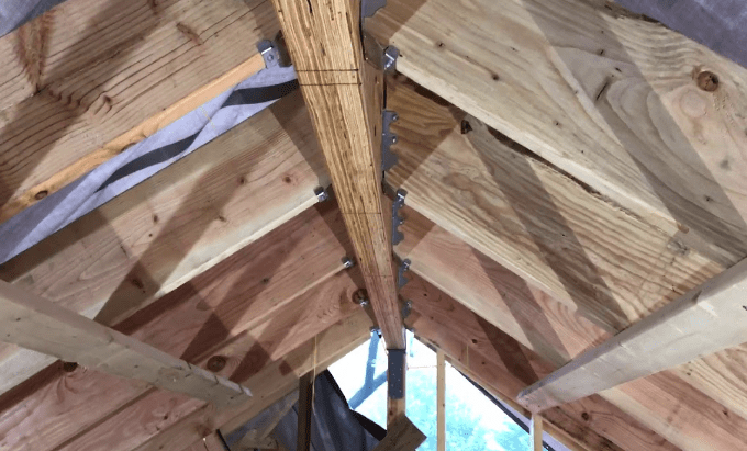
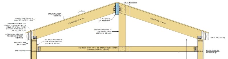
I'm working out a detail for rafter framing (supported by a structural ridge beam). Since I have the structural ridge beam, I don't need to rely on ceiling joists/rafter ties to resist any outward thrust. The client would like to have a dropped ceiling look and I can't figure out which detail to use.

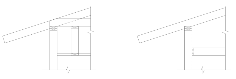
On the left I've created the typical rafter with ceiling joists. From there, I've suspended some framing down to create a dropped ceiling. To me, this adds a lot of unnecessary wood. However, I do like that the ceiling joist is located in the typical spot (although not required for thrust).

On the right, I've created a continuous ledger to support the ceiling.

Note: These details are extremely simplified. This is conceptual only, I realize it's missing a lot of information.

In both scenarios, I'm assuming the top of wall is supported for lateral loads at the roof diaphragm. There will be perimeter blocking between the rafters along the top plate.

Wood is not my biggest strength, am I on the right path here?

Screenshot_2024-09-26_210750_kdt8qe.png
 
Replies continue below

Recommended for you

If it isn't structural it's maybe not your issue to deal with but having an idea when the question arrives seems reasonable. It's an unusual request so it will get unusual construction... usually people want the cathedral ceiling look without a load path, this is the opposite totally, the ridge beam supports the rafters, so a cathedral ceiling is almost the natural approach and they don't want it.

Both look viable but if they wanted a true dropped ceiling have they considered like acoustical tile (and batt insulation laid on top...) IC (insulation contact) rated recessed can lighting....

Insulation depth at eave may influence rafter depth, if you go into that level of effort.
 
lexpatrie,
In your opinion, who's responsibility is it to provide detailing for this work? In the jurisdiction where I practice, wood hand framing is not the norm and you're not likely to find an architect who is well versed to show a certain level of detail. Additionally, the carpenters are not like the folks out of the Pacific northwest, or northeast US, who know every cut (sorry if I left anyone out).

One of the areas I'm trying to determine, is how I'd like the ridge rafters seat over (or frame into) the ridge beam.

Screenshot_2024-09-27_113745_cd5ql2.png


It get's even more specific when the rafters sit on the ridge beam. Does the head of the rafter use a plumb cut where the two ends butt together.
What are the preferred dimensions for the seat-cut and heel-cut at the birdsmouth notch (I know the seat cut needs to achieve the required bearing strength)?
Should I put a collar directly below the ridge beam to help with uplift? If not, how many screws horizontally and vertically can I put into the connection before it's "too many".

Should the rafters overlap instead of butt together?

I'm presenting these sorts of scenarios with the following photos:

1. Rafter seated over ridge beam, plumb cut ends butted, birdsmouth notch.
2. Rafter seated over ridge beam, plumb cut ends butted, birdsmouth notch, addition of collar directly below the ridge beam (helps with uplift?).
3. Rafters overlapped, seated over ridge beam with birdsmouth notch(photo was taken before rafter head was cut in the air).
4. Similar to photo #3, rafter head was cut and nailed together.
5. Rafter with no notch, looks like the ridge beam corners were cut?

Photo 1:
Screenshot_2024-09-27_114733_ouazva.png


Photo 2:
Screenshot_2024-09-27_115323_ijcbvr.png


Photo 3:
Screenshot_2024-09-27_115035_wj4nm7.png


Photo 4:
Screenshot_2024-09-27_115145_xojsim.png


Photo 5:
Screenshot_2024-09-27_120748_owifux.png


As you can see, there are so many variations and it's easy to get lost in the details. I have the book "A Roof Cutter's Secrets To Framing the Custom Home". It's a great resource for the carpenters, but doesn't help me on the actual structural end (with exposure to high wind).
 
I have a very similar condition on a current project. After contemplating it like you, I went with something similar to your option on the right:
dropped_ceiling_nfeysy.jpg
 
You're right, there are endless ways to construct with wood. I almost always use the rafter to ridge connection shown in my detail above (and in the first picture of your post above), with the rafters cut with a single plumb cut and no notch. This seems much simpler than the variations you show above with the notches. It's much more labor intensive with the notches and generally worse structurally. Perhaps if the wood will be exposed, like in your 2nd picture (I'll assume), that would be a reason to do that. Otherwise, I don't think it's a good detail.
 
If you're the structural engineer you should be showing what is needed in the finished product to be stable (this is why I dislike structural drawings that don't show the gypsum board when it seems very likely that the gypsum board is contributing to the stability).

Gingerbread on the exterior, I'd like to see "us" provide the appropriate attachments.

Ceilings that are not involved in stabilizing anything (i.e. rafters), I think it's better to not show the extraneous elements, unless you want to show them to clarify that the design includes their weight graphically. (I probably show these elements personally.)

To delve into your later questions, if you're the engineer whichever connection you "prefer" should be grounded by a calculation, and the specifics are up to you (regarding notches, connection strength, how many nails are too many (when the nails won't fit its too many), and so on.

Thematically the idea is however it's put together you have a wind or snow or roof live plus dead load combination that the member and connections all satisfy. Nothing is really forbidden so long as there's a complete load path and the math checks out via "generally accepted principles of mechanics" (statics, deformable bodies, etc.) And the relevant design standards are held to (shear checks at notches, bearing stress at an angle to the grain, manufacturer notch limits on I joists and so forth, etc.)

For prescriptive construction, the collar tie is not required, as there's an option for the ridge strap.
 
Framers in my area would want to platform frame it...stop the studs with top plates at the ceiling height, and build a knee wall on top of the ceiling joists.
 
TheDW said:
Framers in my area would want to platform frame it...stop the studs with top plates at the ceiling height, and build a knee wall on top of the ceiling joists.
Using balloon framing keeps the calculations easier and is one less step in the framing process.
 
Back
Top