Eng-Tips is the largest engineering community on the Internet

Intelligent Work Forums for Engineering Professionals

Handrail Posts 3

Status
Not open for further replies.

Stenbrook

Structural
Dec 5, 2014
125
0
0
US
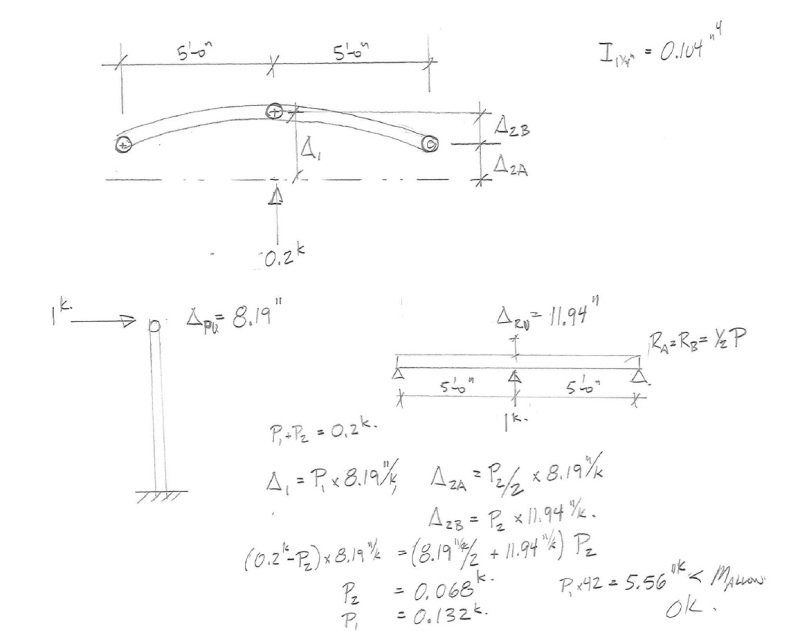
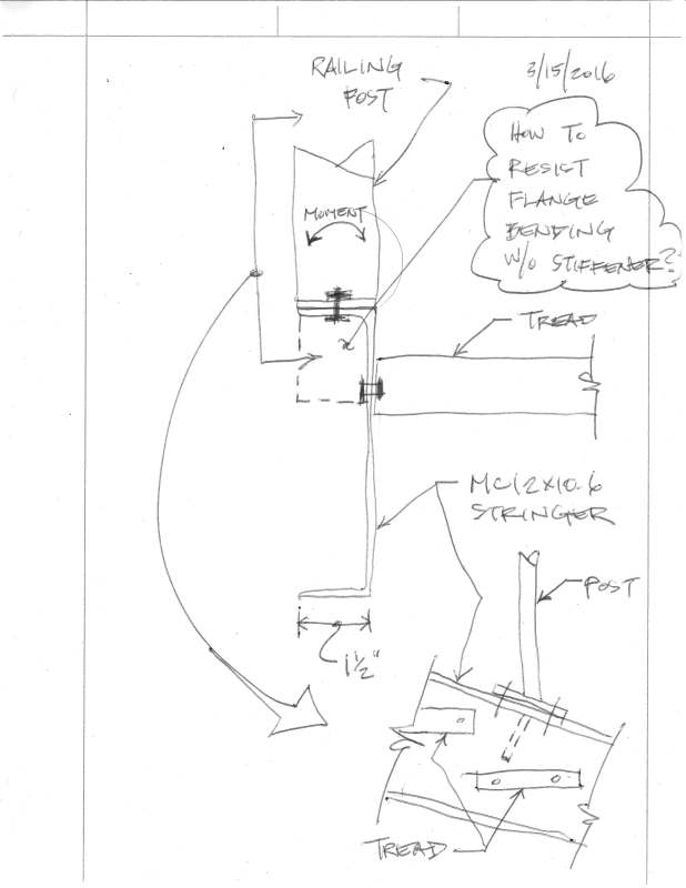
I feel like I am missing something. I have run the calculations on a 3'-6" tall handrail post several times in this delusional hope that the calculations will come out differently but sure enough, they don't. The calcs point to needing a 1-1/2" STD handrail post (which has an O.D. of 1.9") to sustain the required load (50 lb/ft or a 200 lb concentrated load). But time and time again I check stair shop drawings where they call out a 1-1/4 STD pipe. Which, I have checked and absolutely does not work. I assume they do this so they can get away with a smaller stringer size (a MC12x10.6 as opposed to the C12x20.7 which has a larger flange width to accommodate the larger pipe), But I really don't know. Does anyone have any insight into this as to any other reasons why stair manufacturers use these smaller handrail posts ALL the time??
 
Replies continue below

Recommended for you

The NAAMM document uses the 200# load, calculates a moment, and compares it to an allowable moment on the pipe. Not a yield moment, but an allowable moment. (They use an old cold-formed value 0.72*Fy for an allowable bending stress.)

How do 1.25 standard pipe posts work? On paper they don't. We call out 1.25 extra strong pipe for posts, where that OD is required.

Why don't they fail? They probably never see the 200# load. And the material yield stress is surely higher than 35 ksi. I've seen mill certification reports on "pipe" material that was triple certified (A53 Gr B, A500 Gr B, and A500 Gr C) and had an actual yield stress of 65 ksi. That's nearly double the design yield stress.
 
All of my guys use 1 1/4" such 80 posts here with MC12x14.3 stringers which allow for proper welding. I know it's tight, but theses item rest on top of a stinger so you can deduct around two inches from the overall height.

You guys need to push your clients in the right direction or suffer the consequences.
 
But go back to the "words" ... 200 lbs force at the rail (top of post) must not "fail" .. So even IF it bends (yields plastically some how so the rail is bent by a guy running full speed into the rail perpendicular from a room) it has not failed to protect the public from falling.

Handrails are an odd-ball "structure" and are out in the open. They have to be safe, but let's face it. Even that 200 lbsf is an written number in the Code and OSHA that you'd very hard-pressed to justify physically and with measurements of 1000 different people of different weights and ages trying different ways to "fall" through a railing, run into a railing, jump over a railing, etc.

Compared to the tens of thousands of "unknowns" and assumptions affecting the real structural steel of a building and its walls, roofs and floors, surely somebody has tested to destruction 42 inch high vertical posts mounted in various ways to steel channels, steel beams, wood floors, concrete slabs, walls, floors, and sidewalks.
 
Racookpe1978, one could go by your interpretation, or one could go by the NAAMM's interpretation. I prefer the consensus industry authority.
 
As far as I am concerned, we are talking about such a minor increase in steel from a 1-1/4" pipe to a 1-1/2" pipe with respect to a project, and I know that all day long I can justify that a 1-1/2" pipe will work per every code out there. Due to that reason I will continue to specify 1-1/2" Diameter STD pipes and will mark up shop drawings I get that it should be 1-1/2. If they want to use 1-1/4 that is on them, but at least it is on record that I told them to use the 1-1/2"
 
Stenbrook, you need to create typical details for your company showing handrail. In the detail, show 1 1/2 inch pipe. If it goes out with the project, there should be no argument. Well, there still will be an argument ("...we've done it that way for 50 years"... "I've never heared something so stupid"), but it will be in black and white.
We have a detail and we never have a problem.
Now for aluminum handrail and anchorage to concrete, that's a whole different story.
 
Don't forget the human factor. 1.9" OD is pushing the ADA allowed dimensions.

Access Board said:
505.7.1 Circular Cross Section. Handrail gripping surfaces with a circular cross section shall have an outside diameter of 1¼ inches (32 mm) minimum and 2 inches (51 mm) maximum.

ADA Standards
 
I have said details on my drawings. That doesn't stop over 50% of the fabricators from putting whatever the heck they want on their shop drawings.
 
PS: BUGGER, if it wasn't clear the first time around, my post was intended to show agreement with you. That is, to express amazement that something that should be so simple could have this degree of complexity and ambiguity.
 
The 1 1/4" Pipe will work if flanked by posts to both sides. Have a look -

railcalc_urzqr7.jpg


Final deflection is a little over 1"
 
Ok but what happens when you have the 50 plf load acting along the top rail and your posts are at 4' centres. Then the load sharing argument goes out the window.

I don't believe it is realistic to have that 50 plf load along the entire thing but there are code officials out there who may try to enforce it.

Guardrail design around here is typically a delegated item anyway.
 
A couple of ideas I've used:

You can specify 1 1/2" tubing. You can get it exactly 1/5" OD (which the architects like) and it comes in a wide variety of wall thicknesses.

We have a client who put an end to the question by requiring 1.5 x 2.5 rectangular posts with 1.5 square rails. Strong in the posts and easy to fab, alter in the field, grip, and paint.
 
We could design these dynamically like traffic bollards. This would probably be a more realistic approach. Energy methods make it easy.
 
The AISC Specification for Structural Steel Buildings (ANSI/AISC 360) does not apply to the design of guardrails. The industry standards NAAMM AMP 510-92 and NAAMM AMP 521-01.
 
I'm right in the middle of similar calcs so thank you, Stenbrook, for reading my mind. And thank you to all who have contributed well-thought-out responses. My case has 1.5inch square tubes for posts so those are fine, but the connection to the channel flange below has been a thinker. Any suggestions on an approach to make that connection work without adding a stiffener as shown in the attached?
Post_and_Channel_Connection_031516_bmrelo.jpg
 
I think deflection vs failure is where this all breaks down. OBC, which is what I work to, is vague on railing deflections; other codes may be more stringent. I've physically tried to load a residential wood railing with the 1 kN/250lb concentrated horizontal load and it's a lot harder than you might think, and I achieved some pretty good deflection (L/20) without the slightest sign of failure. That leads me to believe that 1 1/4" HSS welded to a channel stringer is going to outperform anything that is contemplated in the code that I have to follow.
 
I did new company standards on this a while back. I wasn't willing to use the assumption of load sharing, because on occasion the hand or guardrails will terminate without some sort of return around a corner. In that case the final post doesn't have an adjacent post on one side to share with.

I also ran into problems with direct mounting on the top of the flange without a stiffener on all possible channel sizes and with some types of clips direct welded to the web of members with all types of web thicknesses. As a result there's a stiffener on the standard detail with a note that it's UNO on the drawings. If someone wants to show that they work without stiffeners for some cases, they're free to do it, and I did it on our standard stair detail, but a standard detail needs to work in all cases.
 
Status
Not open for further replies.
Back
Top