Continue to Site

Eng-Tips is the largest engineering community on the Internet

Intelligent Work Forums for Engineering Professionals

  • Congratulations IDS on being selected by the Eng-Tips community for having the most helpful posts in the forums last week. Way to Go!

Handrail Stanchion Type Baseplate Design 5

Status
Not open for further replies.

dbest69er

Structural
Apr 30, 2012
23
Hi,

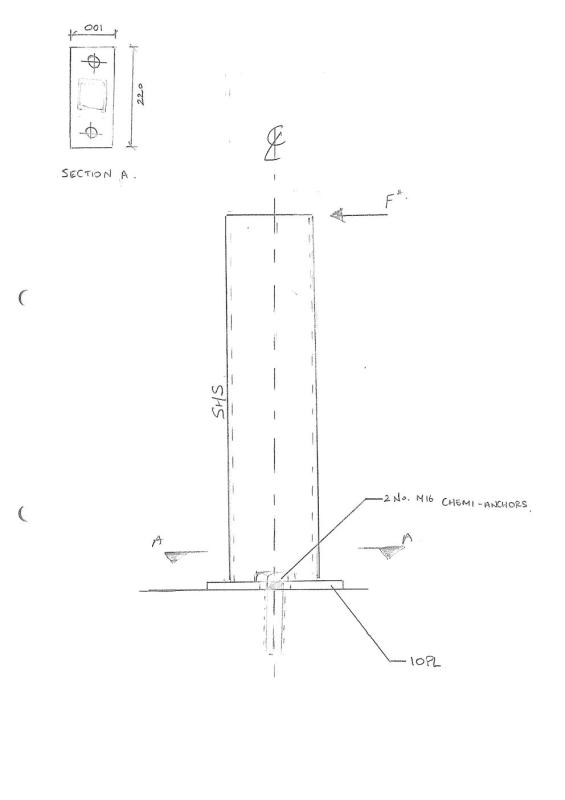
I'm looking at a handrail stanchion type baseplate (where the two anchor bolts are perpendicular to the bending moment).

I'm used to designing moment connections by resolving the bending moment into a tension and compression force and then using this tension force to calculate the size of the base plate to resist bending. In this case, however, there is only one row of bolts in the direction of the bending moment.

I've assumed that the plate will resist the full bending moment in this case. Can someone please verify what I have done:

M* = V x e = 3.2kN x 0.4m = 1.28kNm

Assume base plate (220mm x 100mm x 10THK) is resisting this bending moment:

ϕM = 0.9 x fy x Z = 0.9 x 250 x bd²/4 = 0.9 x 250 x (220 x 10²/4) = 1.24kNm < M*

Is my method conservative? Is there any other way to calculate the plate bending capacity for this scenario?

Thanks!
Sill_Sketch_ur7dfb.jpg
 
Replies continue below

Recommended for you

I don't think PROFIS will calculate the base plate.

It says the following:

"The anchor design methods in PROFIS anchor require rigid anchor plates per current regulations. This means load re-distribution on the anchors due to elastic deformations of the anchor plate are not considered - the anchor plate is assumed to be sufficiently stiff, in order not to be deformed when subject to design loading. PROFIS Anchor calculates the minimum required anchor plate thickness with FEM to limit the stress of the anchor plate based on the assumptions explained above."

I need to perform my own check to ensure that plate bending doesn't occur.

Thanks though.
 
This is a poor design for a base plate. In this case you have to also consider that shear along the line between the bolts and the post will have some effect.

The bolts should be on the back and front of the post, not the sides.

Keep in mind that the primary benefit of guardrail design considerations is how the top rail is anchored. If the top rail is anchored at the ends, there is little bending stress at the base plates. If the top rail is not anchored, the bending stress at the base plate usually exceeds allowables.
 
I'd do it a bit different than what I am seeing here. For one thing, the moment your base plate would see would be a component of "M*" cantilevered to the center line of the bolt group (perhaps even a bit beyond depending on the size of that HSS).

I would have run it myself but it's missing the HSS size....and by the way: does "F*" in the sketch equal "V" in the calcs?

It will need a flexibility check too. (Being that thin, and with only 2 bolts, it's gonna go for a ride.)
 
It's actually an end plate connection for a dropper from a slab soffit that will carry an external (PFC) window lintel.

The horizontal force will come from the wind load on the window. These (SHS) droppers are spaced @1400 ctrs.

The reason the bolts are in this orientation is the fact that we need to avoid PT ducts and having them installed this way would decrease the chances of interfering. Also, this is typically how industrial handrail stanchions are fixed, so it's not uncommon to see this type of connection in practice.

My question still remains, is the calculation I used for the bending capacity valid or is it overly conservative?

Thanks

 
 http://files.engineering.com/getfile.aspx?folder=5eff11b1-931c-4fd2-8ae8-5d69253441da&file=Suspended_Lintels.JPG
@WARose,

The steel sections is 50x3 Square hollow section.

The F* is the shear force being applied from wind load on the external window.

Please note, there are studs located between the SHS droppers to carry external stone cladding. I haven't considered this in the calculation of shear force on each SHS member. I'm not worried about the anchors themselves as these pass all the checks. It's just the plate bending I'm concerned about.

Thanks,
 
Hilti PROFIS Anchor says you need minimum 12mm thick plate.

Capture_poab5o.jpg
 
What stress distribution are you assuming at the interface between the base plate and the concrete? That will determine the bending moment in the plate. Once you've figured that out, you probably need to sketch out some yield lines to check if the plate doesn't fail around the anchors.
 
You also end up with some torsion in the plate which it is not able to resist effectively. That could be a factor if the plate is thin and deflection requirements are tight. If there ain't many of these, just use a thick ass plate and be done with it.
 
Your base plate calculation appears to just be the capacity of the entire plate along the long length, but it doesn't seem to match up with any kind of load path.

Ask yourself, "What is my assumed load path?" When the force is on the tube at the top, how does the moment at the bottom get resolved? It seems to me that the edge of the plate (on the long side) right in the vicinity of the post pushes down and that there is an equal and opposite force pulling at centerline of the post. (This is a little unconservative, as the compression force is not really at the plate edge, but I'm simplifying here.)

So the little part of the plate which extends beyond the post must work in bending to be the path the load takes from the post to the substrate. You can check this by computing the moment as the "down" force at the plate edge times the distance to the face of the post. (This is probably so small it won't control the plate design thickness, but you should check it yourself).

Now, what to do with the force pulling up on the post? It goes into the anchor bolts, of course, 1/2 to each bolt. Now, how does the force get from the post to the bolts? Through bending of the plate. I would take the bending in the plate to be the force in the bolt times the distance from the bolt centerline to the face of the tube. This is the moment which will likely control your plate size. Check your plate for this moment. This is also where the plate will flex, so you might give stiffness some thought here as well.

In reality, the two-way action of the plate is more complicated than this. You could look into some sort of FEM modeling to convince yourself that the simplifications I offer above are reasonable.

Think load path first, then the rest should be easy. If you don't understand the load path, then you are missing the point of being an engineer. And save Profis for the complicated stuff.


Simpson Anchor Designer will design your baseplate. It is very similar to PROFIS.
 
Status
Not open for further replies.

Part and Inventory Search

Sponsor