Continue to Site

Eng-Tips is the largest engineering community on the Internet

Intelligent Work Forums for Engineering Professionals

  • Congratulations KootK on being selected by the Eng-Tips community for having the most helpful posts in the forums last week. Way to Go!

Hardy Panel on Steel Beam

Status
Not open for further replies.

CaPE90

Structural
Jul 31, 2024
7
Hi All,

I have often come to this forum to search for info re: relevant questions and have finally joined. Here is my current situation:

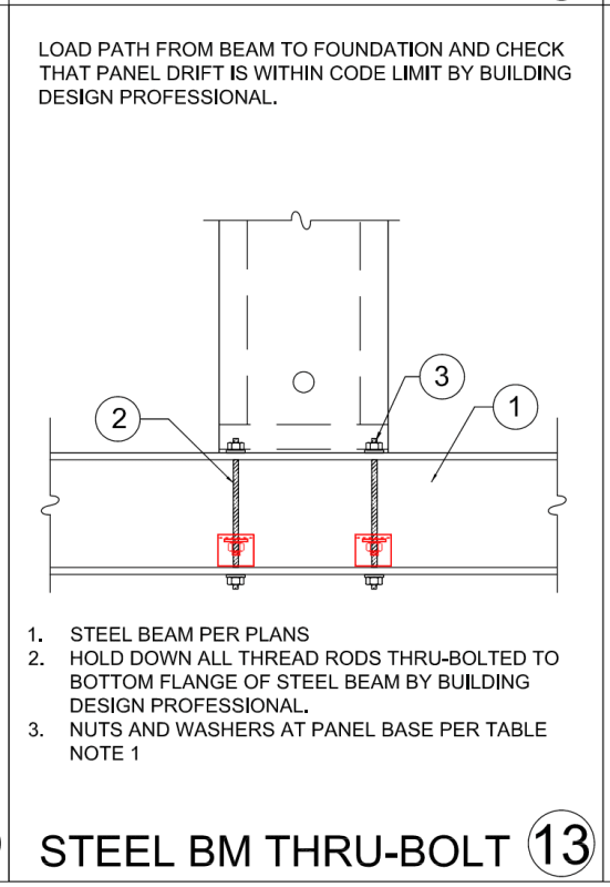
I have two Hardy Frame Panels to be installed on a steel beam in the upper floor of a 2-story residence. My question is regarding the attachment of the Hardy anchors to the steel beam. Mitek wants you to drill thru both the top and bottom flange. They specify the nut and washer above the top flange, and require the design professional to specify the nut & washer below the bottom flange. My problem is the bottom nut & washer would protrude below the bottom of floor framing and may be difficult to conceal within the 5/8" drywall.

Has anyone ever welded to the top face of the bottom flange? And perhaps add a secondary nut & plate washer on the bottom face of the top flange? Any other ideas welcome! I am happy to share loads, sizes, detail, etc as needed.
Thanks!
 
Replies continue below

Recommended for you

I have never used a Hardy Frame but it would likely come down to the bending capacity of the flanges. Why can't you weld a stiffener in and just attach to the top flange?
 
Never used Hardy Frames either, but I looked at the details from here:
Perhaps you could weld some angles above the top flange to raise the attachment point as desired:

Screenshot_2024-07-31_110904_bnyv8o.png
 
Looks like a detail conceived by a draftsman. (not yours, Bones)
I don't get why they run it all the way to the bottom flange.
 
My guess is they want to engage the entire beam cross section, but they leave it up to the EOR to design for the local limit states.
 
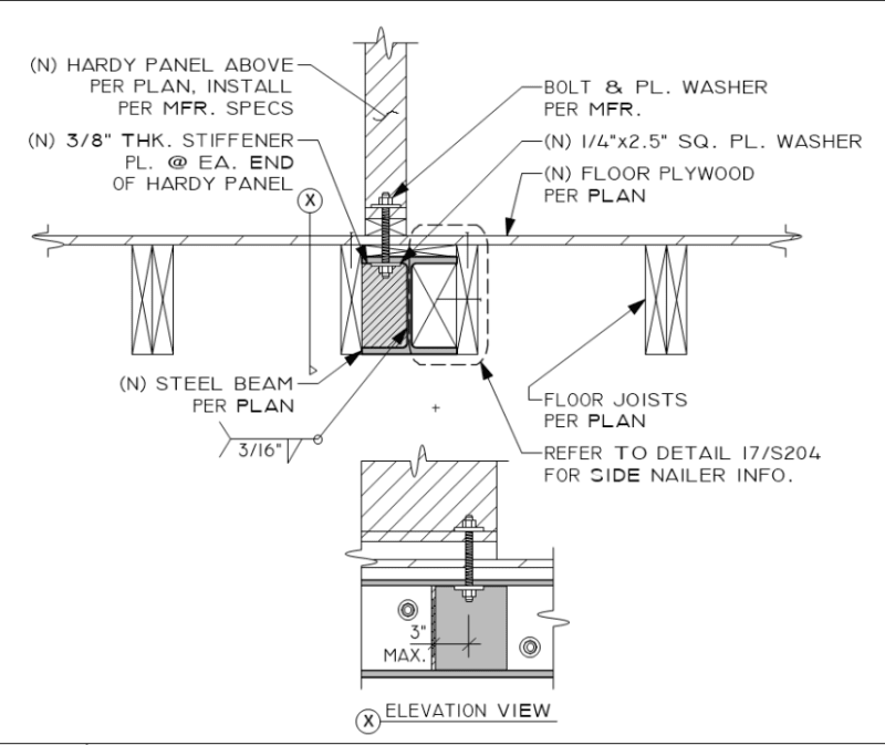
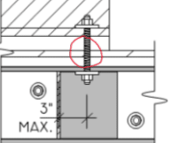
Thank you both for the responses. I failed to mention I had the stiffener plate detailed as well and the Hardy detail makes no reference of one. This should do the trick? I like the angle idea as well but may be not be needed due to the stiffener plate.

deet_fklutr.png
 
Without knowing much here, if I understand correctly that this panel is basically just a shear wall (with tension and compression forces acting at the ends) and I understand correctly that the steel beam is not part of the Hardy system but is designed by you, then I wouldn’t use this detail at all.

I would just add web stiffeners near the bolt locations for the Hardy panel (4 total) and would then bolt to the beam top flange only. This detail seems silly (or I’m missing something). If the loads are low enough and depending on the beam section, you might not even need stiffeners.
 
Now that I see your detail, I might change my response and suggest an alternative solution with the beam centered below. I don’t like the eccentricity here, although perhaps it can be justified.
 
Are you suggesting two stiffener plates be added on the near side, where the anchor occurs? Or one on the far side of the web behind the anchor location? I am going to detail the latter as that stiffener can be directly aligned with the anchor itself. I am reducing the eccentricity on the near side from 3 to 2". This was for workability purposes.
 
Originally, I was thinking two stiffeners on the near side and two on the far side (on other side of web). But that was assuming the beam was centered and also assuming 4 bolts (not 2). With it being eccentric, I would have the two stiffeners on the near side where the bolts are and maybe on the other side as well, although I’m not entirely sure. The far side stiffeners would be beneficial for resisting torsion acting on the beam at that location.

With any eccentricity I might also add solid blocking between the beam and at least the nearest joists to either side. That will help restrain the beam from twisting.

A lot of the particulars for the detail depends on the load magnitude that you need to resist.
 
Aren't the Hardy panels, shear panels? If so, wouldn't the check be to see if the top flange can resist the moments from the shear panel? If just the top flange won't resist, the solution would either needs to be to add the stiffeners as shown or beef up the flange with
I would see no need of the threaded rod needing to be run through both the top and bottom flange if the top flange can be made stiff enough. I would think that Mitek's recommendation is based on not knowing if just the top flange is sufficient and providing a conservative approach to engage both flanges.
 
Heavyside said:
I would think that Mitek's recommendation is based on not knowing if just the top flange is sufficient and providing a conservative approach to engage both flanges.

...except they don't show a nut under the top flange so it is only engaging the bottom flange. Maybe they pulled some engineers from the company that designed the Hyatt Regency :(
 
just weld on a threaded coupler to the top of the beam to accept the hold down threaded rod. center the beam on the wall so it doesn't have any torsion.
 
Won't that get in the way of the bottom of the panel?
 
OP,
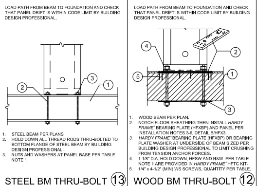
The first note is about the detail the shared. Per Mitek installation details it appears they want the panel flush with the top of the beam. It appears by your detail, there will be a bottom plate, subfloor and nailer that will all be in compression when shear is applied to the top of the panel. Not sure if this is an issue but Mitek's installation details indicates it should be avoided.
p6r9ao3a_bcakft.png

Screenshot_2-8-2024_141030_www.hardyframe.com_rvw34d.jpg

The second note is about how the installation detail appears to show the system working. When shear is applied to the panel, Miket's installation details indicates the top flange will be resisting compression and the bottom flange will be resisting tension. This allows the moment to be decoupled between the top and bottom flanges.
If the top flange is thick enough to resist the couplet, then only the top flange would need to be engaged. Your approach of
Has anyone ever welded to the top face of the bottom flange? And perhaps add a secondary nut & plate washer on the bottom face of the top flange?
combined with the stiffeners, I think would provide a conservative solution but by doing so each flange would be seeing part of the couplet and I would think that this needs to be checked.
 
Status
Not open for further replies.

Part and Inventory Search

Sponsor