SprinklerDesigner2
Mechanical
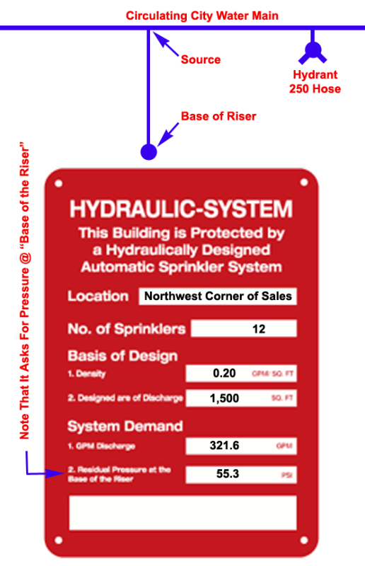
From 1975 I have always filled out hydraulic calculation placards in the following manner.

A plain Jane OH2 grocery store having a 22' ceiling and not having interior hose racks.
I identify the location of the hydraulic calculation area. I know I am right here as I am right to identify 12 sprinklers as in the design area, it surprises me that I find a good number of placards displaying the total number (487) sprinklers on the system, and I know I am correct here as well as I am with the 1,500 sq ft discharge area.
The question comes up with the GPM discharge which I have here as 321.6 gpm which obviously does not include hose streams. My hose stream is 250 gpm but the hose stream is added at the source and NOT the base of riser. True, the GPM discharge doesn't ask for the discharge at the base of the riser but the residual pressure is asked for at the base of the riser.
If I need 55.3 psi at the base of the riser I would need more pressure at the source assuming the elevation of the base of riser and source are the same elevation. It doesn't make sense to me to put 571.6 gpm discharge at the street while using 55.3 psi at the base of the riser when the actual pressure required at the street could easily be 62.3 psi if a long run of pipe or if there's a backflow involved.
And the sign is asking for "discharge" which I interpret as discharge from inside sprinklers and hose streams IF these hose streams are taken downstream of the base of the riser.
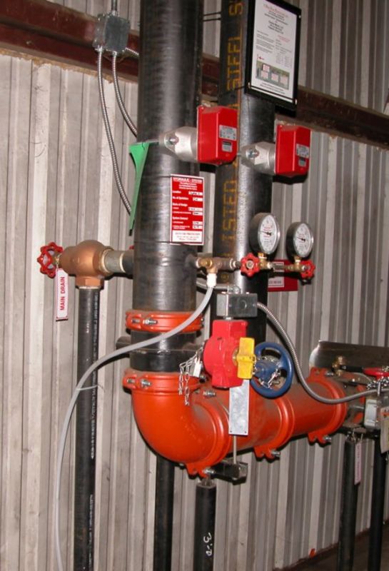
And the "base of riser", where exactly is it? I have always taken it to mean the transition point between the underground pipe and above ground... if we have an 8" DI flange and spigot having a C-value of 140 running into steel pipe having a C-value of 120 then I have always associated my base of riser with this transition point.
Also, while I am rolling along, years ago I ran across an article, can't remember where, that called for gpm's and pressures to be rounded out to the nearest whole numbers. That my placard should read 322 gpm @ 55 psi. Makes sense to me because I find it laughable when I see a placard proclaiming 433.765 gpm @ 67.826 psi. I think Stookey will back me up on this that we're lucky to hit the real number within 5 psi and 10 gpm so what is the point of carrying numbers out to where they look ridiculous?
Also, if their his interior hose stations fed from the sprinkler then I do add the gpm allowance to the overhead at the point of connection for up to two hose racks.
I think part of the confusion comes from 50 years ago when most systems were pipe schedule and we did include hose streams at the base of the riser. Why? I don't know other than that was what the standard called for us to do.
I seem to remember as well we added hose streams at the base of the riser, even if no hose racks or downstream hydrants, for calculated systems from the 1974 standard. Is this "confusion" just a carry over?
So am I right on the placards?
If I am wrong how do you do it?
Oh, and speaking of hose racks. I haven't seen a hose station for occupant use in Georgia for 15 years. The state fire marshal ordered them all removed so people would leave the building and not play untrained fireman. If a company insists on hose stations they may have them but all employees, 100% of all employees event he part timers, are required to attend a several day class at the state fire marshals academy to be trained on how to use fire hoses.


