Eng-Tips is the largest engineering community on the Internet

Intelligent Work Forums for Engineering Professionals

HEAD PUMP - MAXIMUM OPERATING PRESSURE

Status
Not open for further replies.

BACN_mechanical

Mechanical
Mar 11, 2022
6
0
0
EC
If you have a chilled water system with only primary pumps serving a tall building. Also, the expansion tank is located at the top of the building.

How would the maximum working pressure be affected in the following arrangements?:
a. Locating the pumps on the first floor
b. Locating the pumps on an intermediate floor.
c. Locating the pumps on the top floor.

I would believe that the head pumps shouldn't change any of the above arrangements. However, should the working pressure change? Considering that this maximum operating pressure would be mainly affected by the static height.

Also, what other parameters should be considered when changing the location of the pumps?

NOTE: I understand that I don't give you pressure values ​​as in the expansion tank or the head pump, nor heights. But I would only like to know how the system would behave in the three scenarios qualitatively, that is, if it remains the same, decreases, increases, etc.

I'll be grateful for any help you can provide, and success in your activities.
 
Replies continue below

Recommended for you

EnergyProfessional said:
I like to see the system that allows flow at no pressure differential.
This is tangential to the tangent subject here, but if you insist: click your link, scroll down to Figure 4 and see point 4 on the system curve (pump runout). "No pressure drop, 26 gpm flow".

EnergyProfessional said:
Please show us a valid design guide or other resource that recommends installing the ET not near the suction side of a pump.
The why of the thing is the focus of my statements, I haven't made any recommendations at all, merely attempts to correct some statements made that do not agree with my understanding of the subject matter. It seems that my point has been made and the appearance of defensiveness and logical fallacy makes me suspect I have veered into insufferable pedantry, for which I apologize.
 
EnergyProfessional said:
Figure 4 is a pump curve, not a system curve. Google should explain the difference.

I don't think the fact that a pump needs to create pressure in a system needs to be defended.

I agree I should have said 'pump curve' instead of 'system curve' in my sentence above, but comments like "Google should explain the difference" that toe the line of personal attack are entirely uncalled for.

To remove my terminology error and state it more clearly and correctly, point 4 is where the system curve of system 4 shown in the inset intersects the pump curve. This is an example of a system that allows flow with no DP, as you requested.

No one is denying that in any useful closed loop system a pump will generate DP. I was trying to illustrate the point that it is entirely possible to turn on a pump and have the loop pressures decrease in response (by installing an ET directly at the pump discharge connection). I am not saying that that is advisable to actually do so, my intent with all of this was only to correct the misunderstanding that a pump in a closed loop is capable of compressing the membrane of an ET located at the pump discharge, or anywhere else in the loop for that matter.

 
Dear experts

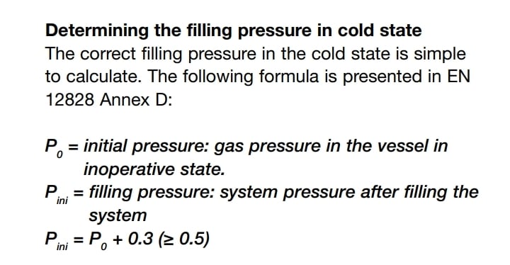
I have read some manuals from different expansion tanks' manufacturer and they have mentioned the expansion tank air side pressure should be 0.3 bar higher than the static pressure of the point to which the tank is connected.
If the air pressure of the tank is the same static pressure that the tank is connected to then likelihood of filling the tank with water is too high although the water has not been warm or expanded.

Screenshot_20220731_095855_mer6xb.jpg


The same formula from CALEFFI company
 
Do you apply the above formula into practice or only charge the expansion tank just the same static pressure as the point it is connected to?
 
Status
Not open for further replies.
Back
Top