dopetraveller
Student
- Feb 21, 2025
- 3
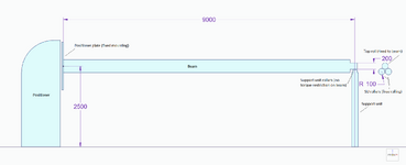
Hello! I'm a mechanical engineering student and I'm designing a welding fixture for a headstock type positioner. The positioner can support 20 000 kg a with deviation radius of 165 mm. This positioner is fixed with no tilt mechanism and its max torque is 25 000 Nm. The positioner has a support unit which max load is also 20 000 kg and the manufacturer of them claims they have a max combined load of 40 000 kg. The support unit is a free rolling type with such a mechanism where two 200 mm rolls support a third 200 mm roll on top of them forming kinda like a triangle structure. The top most roll is attached to a workpiece or in my situation the welding fixture. The 2 rollers on the support unit have a machined surface which face is curved. The curved design allows for a controlled flexing of the workpiece/fixture and it also keeps the contact area small and consistent. Also the supposed max length of the workpiece/fixture can be 13 m with the support unit as stated by the manufacturer.
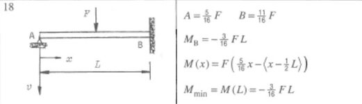
Now with this information I imagine that if I were to create a perfect situation for the positioner and attach a beam in the center of the turning radius which center of mass is perfectly in the middle of the positioner and support unit. This would create a situation which could be compared to a propped cantilever right? The torque created by the beam is controlled by the fixed mounting to the positioner table and the support unit only provides support from the bottom. Techically there would also be some kind of friction force which is created by the contact area of the free rolling mechanism but this would be quite negatable.
The problem I am facing is that the manufacturer has provided information which contradicts my calculations with this design. It is said that the max positioner table tilt torque is 70 000 Nm. In a situation where the beam is 10 meters long and weighs 10 000 kg the calculated torque at the point where the beam is connected to the positioner table is over 180 kNm. This value is way more what the positioner can handle? Also we are no where near the said weight limit of the positioner not to even mention if we take a real life scenario into consideration where the center of gravity is more off center.
I have yet to contact the manufacturer since it's sunday but I am very confused at the moment. All I can think about is that either I missed something importand or just understand the situation very wrong or there is a major mistake with the provided information by the manufacturer of the positioner.
For more information I'm designing the fixture out of SHS beams and it is impossible for me to determine the geometry of the needed fixture because I need to make sure that it is cabable handling the loads from the workpieces attached to it while also at the same time not crossing the line which the positioner is cabable to operate at. The fixture needs to be off center so taller pieces can be rotated and the 40 000 kg max capacity is not needed since the heaviest workpieces will be at max 10 000kg (this weight doesn't include the weight of the fixture which would be something like 3-4000 kg)
Sorry for any spelling mistakes, english is not my first language.