Eng-Tips is the largest engineering community on the Internet

Intelligent Work Forums for Engineering Professionals

Healthy Phase Voltage Sag During Fault 1

Status
Not open for further replies.

protoslash

Electrical
Jul 19, 2018
67
0
0
CA
Hi

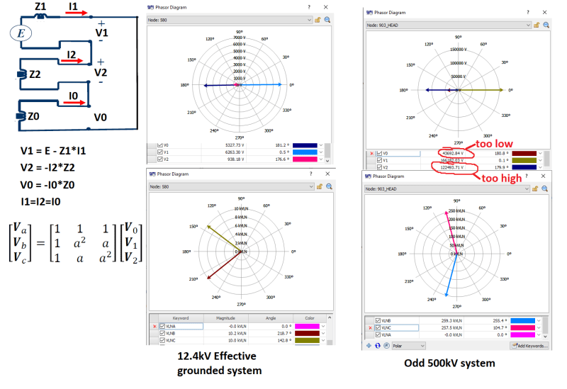
I have an effective grounded 500kV system. If I apply a single phase to ground fault, I expect the fault phase to ground voltage to be 0 at the point of the fault, while the other two healthy phase to ground voltage to increase (amount affected by system grounding).

However the simulation actually shows the healthy phase phase to ground voltage also decreased at the point of the fault. Anybody have an explanation to why the voltage decreased instead of increase?

fault_rgpfoe.png

fault2_axprpp.png
 
Replies continue below

Recommended for you

Do you have a delta winding in the transformer?
A delta winding coupled with a grounded wye winding will transfer power from the healthy phases to the faulted phase.
The resulting voltage drop may be more than the voltage rise across the fault impedance.

--------------------
Ohm's law
Not just a good idea;
It's the LAW!
 
That's getting into under the hood secret sauce types of things. If you're going to get an actual answer it will have to come from the technical support folks at the software vendor. All of them make assumptions about how real sources actually work. If you have just local generation you can get reasonably close if you have all of the generator parameters. But if "source" is some composite utility source away from generation they could be doing most anything. One of those examples of the expression that "all models are wrong, some models are useful". In your case that isn't useful, but the model might well be good enough further away from that source. Talk to the vendor.

I’ll see your silver lining and raise you two black clouds. - Protection Operations
 
If your 500kV system is EFFECTIVELY GROUNDED then you SHOULD not get higher voltages on the healthy phases because the earth fault factor (Coefficient of grounding)
at the fault location is less than 1.25 (85%). That is the meaning of Effectively or legitimate grounding so that X0/X1<3 & Ro/X1<1.
But if your system is HRG or LRG system then during a ground fault, depending on the X0, X1,& R0 values at the fault location, X0/X1 & R0/X1 ratios may not satisfy the condition X0/X1<3 & R0/X1<1
(specially R0/X1<1). In that case the voltages of the healthy phases can go up to the full line to line voltage so that calculated EFF (COG) is 100%.
 
ok PSCAD support was no help, but at least I understand mathematically why the healthy phase voltage can drop during SLG fault.

For phase A to ground fault, connect the sequence network in series blah blah, we can calculate V1 V2 V0. Typically Z0 is higher than Z1 (also satisfying X0/X1<3), this leads to magnitude of V1 > V0 > V2. Also V0 and V2 are in phase while V1 is 180 degrees out of phase. These sequence vectors results in a typical effective grounded system voltage we expect. (see diagrams below)

However for my source equivalent shown up top, the Z0 is much lower than Z1, this results in higher I0. When you calculate V1, V2 and V0 again, now magnitude of V1 > V2 > V0. Converting back to phase quantity, the Vbn and Vcn will decrease under 1 pu.

I got these source impedance from the Utility, they said it was accurate and I have to assume it is. Even tho I can explain the voltage drop mathematically, I still can't come up with an intuitive explanation.
Bonus point - i tried this is multiple modelling software and they got the same result. I have to assume system actually behave like this in real life. Folks here can run the numbers with the source equivalent in the original post to verify.
fault3_rcbfjl.png
 
The source zero-seq impedance could be lower than the pos-seq impedance if you are close to a delta-grd wye transformer source. With the delta-grd wye transformer in the network, zero-seq impedance of the system on the primary side of the transformer is shorted out.

This is why the phase-grd fault current is higher than the 3-phase fault current when you are close to a distribution substation. Line zero-seq impedance is higher than pos-seq impedance, so the phase-grd fault current decreases faster that 3-phase fault current as you get further from the substation.
 
Yes i agree, it is realistic for phase to ground current to be higher 3 phase fault current for those reasons. I just never considered/understood the voltage impact of it.
 
In my opinion, waross's question is legitimate.
I think it's a step-up transformer d11Yn 20-22/500 kV connected with a power plant -my experience- and in this case the voltage drop in the low voltage part is transmitted on high voltage part.
 
no it has nothing to due with the delta windings. This happens when zero sequence impedance is lower than positive sequence impedance or single phase ground fault current is higher than 3 phase fault current. It could happen on distribution system too as mentioned above, you can open circuit the entire load side and the only current flow is from the fault to result in the same voltage drop on healthy phase.
 
The only place I can think of in a real power system where the zero sequence would be less than the positive sequence is near a transformer bank with a delta connected winding. Theoretically large generators have low zero sequence impedance but they typically are high-resistance grounded so the zero sequence impedance is huge.
 
Status
Not open for further replies.
Back
Top