bernardirafael
Mechanical
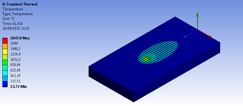
I managed to solve the problem of my last thread here, but now I am having another one. The Workbench is plotting the heat source and it is clearly heating the plate, but it seems that the results of the last substep are not being considered on the next one. As the heat should be propagated through a great part of nodes/elements, it is only next to the heat source (see image below for better understanding).

It should be working like this:

As you can see, the heated zone should remain with a higher temperature over time, until it cools down entirely. Unfortunately, it is not happening on my analysis, since the heat source moves along with your effect area but it seems that it's not accounted for the next substep.
Here is my code:
Any ideas on how to solve this problem? What am I doing wrong?

It should be working like this:

As you can see, the heated zone should remain with a higher temperature over time, until it cools down entirely. Unfortunately, it is not happening on my analysis, since the heat source moves along with your effect area but it seems that it's not accounted for the next substep.
Here is my code:
Code:
CMSEL,ALL
*GET,EMAX,ELEM,,NUM,MAX
*GET,EMIN,ELEM,,NUM,MIN
ALLSEL

AUTOTS,ON

TIME_WELD=200
DT=1
A=0.003
B=0.004
C1=0.004
C2=0.016 !A, B AND C ARE JUST THE HEAT SOURCE DIMENSIONS
TAU=0 !TIME DELAY
FF=0.4 !FRACTION OF HEAT ON THE FRONT PART OF THE HEAT SOURCE
FR=1.6 !FRACTION OF HEAT ON THE REAR PART OF THE HEAT SOURCE
Q=3840 !WELDING ENERGY J/S (W)
VEL=0.002 !WELDING SPEED
EE=2.71 !I HAD TO DEFINE THE EULER NUMBER AS 2.71 INSTEAD OF USING exp() DUE TO UNSTABILITIES ON MY RESULTS

NPT=TIME_WELD/DT

*DO,ii,1,NPT,1 !TIME INCREMENT
WTIME=(ii/2)
TIME,WTIME

HCENTER=VEL*WTIME !HEAT SOURCE CENTER

*DO,jj,EMIN,EMAX,1 !SELECTS THE CENTROID OF EVERY ELEMENT

X=CENTRX(jj)
Y=CENTRY(jj)
Z=CENTRZ(jj)

CSI=Z+(VEL*(TAU-WTIME)) !MOVING COORDINATE (IT MOVES THROUGH Z AS TIME PASSES

*IF,Z,GT,HCENTER,THEN !DEFINES WHETHER IT'S THE FRONT PART OF THE HEAT SOURCE OR THE REAR PART

C=C1
F=FF

*ELSE

C=C2
F=FR

*ENDIF


PART1=(6*(3**0.5)*Q*F)/(A*B*C*3.14*(3.14**0.5))
PART2=(EE**(-3*(X/A)**2))*(EE**(-3*(Y/B)**2))*(EE**(-3*((CSI/C)**2)))

QF=PART1*PART2 !HEAT SOURCE EQUATION

BFE,jj,HGEN,,QF

*ENDDO

SOLVE

*ENDDO

CMSEL,ALL
BFEDELE,ALL,ALL
ALLSEL
Any ideas on how to solve this problem? What am I doing wrong?
