Eng-Tips is the largest engineering community on the Internet

Intelligent Work Forums for Engineering Professionals

  • Congratulations waross on being selected by the Tek-Tips community for having the most helpful posts in the forums last week. Way to Go!

Heat Transfer calculation problem with overall heat transfer coefficient

Status
Not open for further replies.

kfoh

Aerospace
Mar 19, 2015
9
0
0
NL
Dear all,

I just found that I made a horrible mistake in my calcualion for a phase chaning heat exchanger desing. For the design i wanted to include the change in physical properties, for which I decided to create the heat exchanger in a discretized manner. I did this and calculated the heat transfer coefficient on each side, which was no problem. but depending on the step size I chose, the entire length of the heat exchanger varies, since the formula for the overall heat transfer coefficient apparently can only be used on the total length of the exchanger, which is of course not possible since it is unknown.
The formula I used for the overal heat transfer coefficient is the following:
formula_eaeteh.jpg

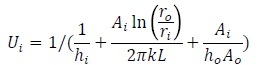
The areas Ai and Ao I calculated are of course in the discrete way of my design a function of the stepsize dx. With this the overall heat transfer coefficient changes strongly with stepsize, leading to a different length of the overall exchanger (I fixed a required output temperature, based on the saturation temperature of one of the fluids).

Now I dont know how I can calculate the change in heat of the fluids. Before I was using the following formula to determine the change in temperature of the two fluids:
formula3w_romcif.jpg


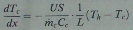
Is there any option how I can determine the change in temperature when I do have the crosssectional geometry, heat transfer coefficients and the bulk fluid temperatures, but not the entire surface area of the exchanger?

Thank you already for your help!
 
Replies continue below

Recommended for you

I am not sure I understand the entire problem. If there is a phase change then one of the temperatures remains constant at the saturation temperature until all fluid is boiled into vapor, if it is a single component liquid. If it is a 2 component fluid ( ammonia + water, propane + butane, etc) then the saturation temperature would vary with concentration of the 2 constituents.

Most commercial HX's use only one tube size and one wall thickness , so Ao/Ai is a fixed value, and it does not vary. If it is a boiling fluid you may wish to use a smaller diameter tube at the liquid end and a large diameter in the 2 phase end ( to improve the thermal hydraulic sensitivity or flow unbalance).

"Whom the gods would destroy, they first make mad "
 
Thank you for your reply!
The phase change however starts somewhere within the heat exchanger. before and after there are single phase fluids since LNG does not enter at saturation temperature. I am using a mixture between methane and ethane to model an LNG flow. For the work I do it is okay to assume the temperature along the phase change to be the same.
in the term of the above mentioned equation in which the Ai/Ao is written I agree with you that it doesn't matter what the lenght of the exchanger is since it cancels out. However there is an additional Ai term, in which the length is important.

I do model the heat exchanger based on an energy balance. I do that stepwise with a step size dx. Based on the heat transfer coefficients and flow parameters there is a certain heat exchange between the fluids. The properties of a fluid exiting a section are taken as input to the next section. By knowing the number of steps it took to reach the required exit temperature and the lenght of each step I know the total length of the heat exchanger(No_steps*dx=total length). So far I used the area Ai and Ao based on the step size dx, so dx*pi*2*r was the area. However depending on the lenght of dx i chose, the formula of the overall heat transfer coefficient gives different results, which again leads to different overall length of the heat exchanger, which makes no sense. I do not know now how to evaluate the overall heat transfer coefficient...
 
As a general guidance, I should state that what you are trying to do is a marriage of heat transfer, thermodynamics and fluid dynamics.

Heat transfer textbooks have a section on heat exchangers, therefore, you'll need to reference such book to utilize or modify relevant equations.

Thermodynamics will involve the calculation of enthalpies probably, in your case, at the outlet of the fluid being heated by using the first law. Of course since you would have knowledge of temperatures and pressures at inlets, then enthalpies of both fluids would be easily determined from the fluids phase charts or their Mollier diagrams.

Pressure drop calculation using fluid dynamics equations should help in approximating the outlet pressure of one or both fluids from which enthalpy(ies) can be determined, as long as its (their) temperature(s) is (are) known, from the fluid phase chart(s) or Mollier diagram(s).

Back to the first law then the enthalpy of the other fluid at outlet can be approximately calculated if the pressure drop calculations could only be carried out on one fluid.

The Mollier diagram of the fluid of interest can then be utilized to determine the phase (liquid, saturated or superheated vapor)
at exit of heat exchanger.
 
I should also state that since the value of U will change throughout the length of the heat exchanger due to temperature changes, I would deal with only bulk temperatures for both fluids and forgo the discrete analysis until such time that once the analysis involving bulk temperature is complete, then you can get into the discrete analysis involving similar steps.
 
Dear chicopee,

thank you for your elaborate reply. I actually found out that in formula 1 I depicted, there is an error I think. When making a dimensional analysis it becomes clear that the area factor is missing on the left hand side. After fixing that, this issue was solved.
With regard to the pressure drop calculations, I split my entire program in three parts. I calculate the single phase pressure drop according to text book theory, since it is there given as an function of the pipelength (which I take to be the lenght dx). The two phase pressure drop I take from Martinelly and Mueller-Steinhagen and Heck.
 
Status
Not open for further replies.
Back
Top