Continue to Site

Eng-Tips is the largest engineering community on the Internet

Intelligent Work Forums for Engineering Professionals

  • Congratulations cowski on being selected by the Eng-Tips community for having the most helpful posts in the forums last week. Way to Go!

Heat Transfer Coefficient Calculation 3

Status
Not open for further replies.

ghost_rider

Mechanical
May 3, 2018
12
I have a copper coil wrapped around a stainless steel cylinder (please see attached). The temp. of inner surface of the cylinder is assumed to be 500C. Water will flow through the copper coil, entering at 20C and leaving at 60C (therefore the average water temp is 40C).
Now for the heat transfer from the coil wall to the water inside, Q=U A dT (W) can be used? I'm having difficulty in calculating U. Here, the area is the surface area of the coil. But, should dT be the difference between coil wall temp and avg. water temp? Before that, can I use same equation to determine heat transfer between cylinder and coil outer surface? Again, I'm having difficulty in U calc.

Once I have Q, I can use it to calculate the water flow rate required to achieve a gradient of 40C (60C-20C) for Q=m(mass flowrate) Cp dT (W)
It will be really helpful if anyone can please advice on U calculation. Also, on the method I have used to get flow rate.

Note: fuel is burnt inside the cylinder. However, to simplify the problem I am assuming the inside wall temp will be 500C.
 
 https://files.engineering.com/getfile.aspx?folder=a5469b2c-022e-4563-9775-12203979f8cf&file=1.png
Replies continue below

Recommended for you

Thanks. If the water flow is laminar say Reynolds number is around 1000, according to wikipedia a Nu of 3.66 is assumed for constant surface temperature for circular tubes or 4.36 with uniform surface heat flux for circular tubes. How valid is this assumption? I would like to check a case of low Reynolds number as well. But, if Nu is constant then iteration is not needed.

It seems that the iteration process is valid for Tfilm < boling point, as the properties of water are evaluated at Tfilm. I am using CoolProp database and Matlab script to iterate. It is working, however, Tfilm > boiling point is fetching density of water at gaseous state. Therefore, the final value of Twall does not seem accurate (Dittus-Boelter equation is not valid ?!). I am trying out different input for velocity, tube dia, etc. My initial guess for Tfilm is always less than BP. I guess I need to set a criteria for Tfilm.
 
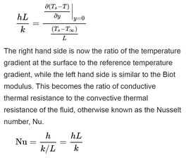
If you look more closely, you'll see that the Nusselt number is proportional to the derivative of the boundary layer temperature vs. distance divided by the temperature gradient, which makes it temperature dependent, however slight that might be.
nusselt_cnohux.gif


TTFN (ta ta for now)
I can do absolutely anything. I'm an expert! faq731-376 forum1529 Entire Forum list
 
OP said:
Tfilm > boiling point is fetching density of water at gaseous state. Therefore, the final value of Twall does not seem accurate (Dittus-Boelter equation is not valid ?!)

This is because your "assumption" that this single, small-diameter copper tube at a flowrate slow enough to allow/maintain laminar flow is not boiling is incorrect. The proposed solution (single copper coil at low flow) is unsafe, liable to steam bubbles and vapor lock, if not steam production and blowout.
 
The analysis is taking a good shape now. Thank you everyone for the valuable inputs.

One query to @georgeverghese,

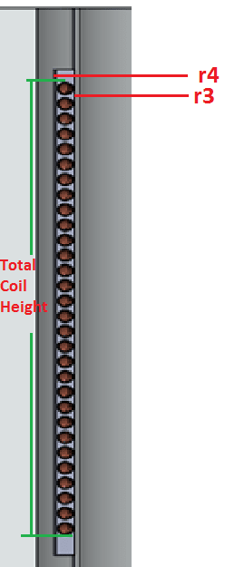
For the resistance in the thermal cement, I have assumed a concentric thermal cement where the copper tube is buried (as you suggested previously).

R = ln(r4/r3)/(2*pi*kcement*L)

My assumption for the L is the total coil height. Any suggestions on my assumption would be helpful.

Hopefully, limiting the film temperature to maximum 95C will be enough to prevent steam/two-phase problem. Currently, working out different tube sizing, flow velocity to achieve the desired bulk temp.

1_xdikaf.png
 
By definition, to get the total surface area of the tubes, L is the total tube length.

One of your key assumptions is this 500degC for the inner surface of the cylinder, which will have to checked. Is this the worst case surface temp? This will most likely have an impact on the tube ID film temp.

 
For the surface temperature, what I have done is that the main equation was rearranged to get surface temp in terms of wall & bulk temp. This gives me the maximum surface temp for the assumed flow rate, film temp and bulk temp. With my current parameter, the maximum well below the 500C I
had assumed. Obviously, having a very low k value for the cement will increase the max. temp.

Ts=((1/(R3*UA))*(Twall-Tbulk)+Tbulk)

R3= 1/hc*Ai

As you can see from the image below, the copper tube is buried inside a concentric (with the cylinder) thermal cement with height Lc. For the first term in the right hand of the eqn, L is the cylinder height. For the 2nd term, I initially assumed the length to be equal to coil height (slightly smaller than cement layer height Lc). I am confused that if this is a valid approach or the cement should be concentric with the tube (in that case less thermal contact with the cylinder!?). This is the last piece of this puzzle. I have validated the approach assuming a low surface temperature, to get the wall temp.

The tube length is used to calculate the inner surface area of the tube.

r_wp0gox.png
 
Status
Not open for further replies.

Part and Inventory Search

Sponsor