Continue to Site

Eng-Tips is the largest engineering community on the Internet

Intelligent Work Forums for Engineering Professionals

  • Congratulations KootK on being selected by the Eng-Tips community for having the most helpful posts in the forums last week. Way to Go!

Heat Transfer with the sea

Igor D

Student
Dec 13, 2024
6
Greetings from Brazil,

I am trying to build a spreadsheet to estimate how cold a fluid would be at the end of a pipe.

This non-insulated steel pipe (let`s say ~3000ft long), would be vertical in the sea, from surface to sea bed. At surface a pump would pump down, with a certain constant flow rate.

This is out of my expertise, so I`d like to have some guidance from the community.

Initial doubts, on how to work it (but please advise):

1. I am thinking about dividing this 3000ft long pipe into ten 300ft sections. So I`d solve them separately in a sequence, from top to bottom. Each 300ft section would have a constant sea temperature along it, for simplification.
2. Sea water gradient goes from ~80degF at surface to ~40degF at ~600ft, where it would remain, at least for simplification, at a constant temperature of 40degF until the sea bed.
3. I don`t know how to treat the sea here. I`d like to assume it never heats up (even very close to the pipe) for simplification. I think I could say it is a constant heat (cold) source. Please advice.
4. Because of friction, fluid would generate heat as it flows down (I`d be pumping sea water, for simplification, if any).

Doubts on how to iterate it:

T=to
static conditions before start pumping down

T=t1
1. solve the first 300ft section
- assume fluid enters this section at 80degF and after moving the entire 300ft, the final temperature is the heat generated by friction plus initial temperature minus heat lost to the pipe which is at sea temperature

2. do the same for all other 9 sections, using for each section the average sea temperature at depth as the initial temperature
- after all 9 sections have been calculated, this is the end of iteration 1 (end of T=t1)

T=t2
1. again, solve first 300ft section
- here I am lost, as fluid enters the top of the first section with the same temperature from surface (80degF), but how do I take into consideration the exit temperature already calculated on the previous iteration? If i don`t, this temperature will never change and I think the iteration converges and freezes.

2. solve the second 300ft section (and repeat for the other sections)
- initial temperature for each section is the exit temperature of first section at T=t1

Please advise the formulas to be used. I was reading INCROPERA chapter 8 about internal flow and think that maybe the constant surface temperature approach could work.

Thanks,

Igor
 
Replies continue below

Recommended for you

I would treat the water as a naturally convected cooling fluid, but otherwise, I'd be doing something similar. Your confusion arises because your approach is a steady state solution, so there is no time iteration required.

Are you trying to do a transient analysis? That would only apply for the time = length/flow_rate; after which, the steady state solution applies.
 
Hello,

Thanks for the reply,

I don`t think I care if this is a transient analysis, but because the sea temperature varies with depth, I don`t know how to calculate for the entire length, thus the iteration seems the way to go.

Another point that creates confusion for me, because of my ignorance on the subject, is: if I am trying to solve for the final temperature, how can I calculate q?

Would you consider this example a constant surface temperature approach or a constant q approach?

Thank you,

Igor
 
I don't have time to look at right now but I believe it can be approached this way.

Q = U*A* delta T

U is overall heat transfer coefficient consisting of three layers: inside convection film, pipe wall, and outside convection surface film. Note that for curved pipe surfaces there are methods to determine the effects of the curve surface on the overall U-value.

A is surface area of pipe.

delta T is temperature difference along the pipe between inside of pipe (fluid temperature) and outside of pipe (seawater temperature). You could model by using discrete pipe segments as you indicate but I would use much more segments as it is easy to copy and paste calculation lines in Excel so I would divide say into 5 foot segments.

However I believe delta T for this arrangement can be converted into a log mean temperature difference (LMTD) as this is a very simple configuration for heat exchange. If you calculate the LMTD you can plug into the above equation without having to break up into segments and get the answer directly.
 
Last edited:
- here I am lost, as fluid enters the top of the first section with the same temperature from surface (80degF), but how do I take into consideration the exit temperature already calculated on the previous iteration? If i don`t, this temperature will never change and I think the iteration converges and freezes.
Are you trying to calculate the local sea water temperature change? But you already assumed that sea water temperature does not change.
So what is the purpose of more than 1 iteration?
 
Surely this is just a steady state calculation not an iteration as there is no feedback of any fluid?
 
Pls read up on natural convection over vertical pipes in your Uni heat transfer text. All required formulas for this will be in these books. Else a concise treatment on this is in Perry Chem Engg Handbook in the section on Heat Transfer.
There are 2 resistances acting in series ( at least) here:
(a) the internal forced convection mode heat transfer coeff hi
(b) the external natural convection mode heat transfer coeff ho

The pipe metal wall htc can be ignored. Include any additional resistances from outer cement or HDPE layers as required.
 
1. Fouling of the pipe exterior by mineral and biological sources will reduce the effectiveness of the heat transfer.
2. Unless you conduct a transient analysis, you will not be able to determine the flowrate that can be sustained. Your steady-state approach does not allow you to determine how long it takes to reach the new thermal equilibrium in each segment.
3. Is the point of this exercise to create chilled water that will be pumped back to the surface? If so, the water will warm back up as it returns to the surface without proper insulation (which will pose some difficulties).
 
Ocean water temperatures vary with depth, as noted by the OP, AND WITH LATITUDE.

Deep water (below 200 m) will be roughly constant, varying from 4 to 5 C as a steady-state condition. This is independent of latitude.
However, surface temperatures are directly affected by the amount of sunlight and the angle of incidence. This results in a "high" near the equator of about 30 C, down to a "high" near the poles of about -2 C. The temperatures noted above are not seasonal, by the way.

Also remember that the pumping would be under some pretty high pressures which may impact the internal friction calculations - at 1000 m depth, the external (sea) pressure will be roughly 9120 kPa.
 
- here I am lost, as fluid enters the top of the first section with the same temperature from surface (80degF), but how do I take into consideration the exit temperature already calculated on the previous iteration? If i don`t, this temperature will never change and I think the iteration converges and freezes.

Not as lost as most of us are I think. You only say you're pumping from surface to seabed for some unknown reason.

Hence why would the exit temperature at the end of the pipe have anything to do with the entry temperature at the start of the pipe??

This is where a simple diagram might help us all understand what it is you are trying to do.
 
Hi, thanks for all the replies and specially for your patience with my ignorance.

@Snickster suggested to use a series of 3 coefficients to have a single U and break down into smaller sections. But my lack of experience with this type of problem is confusing me.

1. For simplificatiom, I wanted to assume the sea is to big to be influenced, which would imply it is a heat source (in this case a cold source, as it is colder than the fluid flowing inside the pipe). In this case it would provide a constant negative Q to the system and its heat coeficiente would not be part the system.

2. If I try the above approach, I cannot solve the equation Q = U*A*deltaT, as I don`t know what is the final temperature neither what is the Q the sea is providing.

@goutam_freelance @LittleInch : I would be happy to solve the system in a single line/equation (end state or static approach), but I don`t understand how. I think to do that, I would have to use something like:

q * pi/4 * (De^2 - Di^2) * L = m * Cp * (Tf - Ti)

Heat through the pipe volume = mass flow rate * fluid heat capacity * deltaT

But in this case I don`t know what`s the q, neither the final temperature (which is what I want to solve for)

@dvd I am simplifying this exercise, no external incrustation, and there will be no flow back to surface. This is just an exercise so I can learn the basics.

@Gr8blu I am simplifying this exercise, but I understand surface sea water temperature changes with Latitude. I was thinking to solve the Pressure drop/friction/heat generation before I solve for Heat Transfer (and include that "heat per meter" due to friction in the heat transfer calculation later).

This is the point where I think, breaking into sections would help: The fluid being pumped would slowly heat the pipe because it is warmer than seawater/pipe and friction would help a little in keeping it warm, especially closer to the surface. But as it moves down, it would start losing heat to the cold pipe (being fed by a negative heat source, the sea). If the pipe is short enough (and I don`t know how short it would be necessary), fluid exiting the bottom of the pipe, would still be above 40degF.

@LittleInch : yes it is an unknown reason, for me to learn. This is a 1st step, but later on I want to further complicate and will be pumping inside a subsea well where the pipe willl be surrounded by the earth; and now the earth will warm the fluid back as it goes deeper. Bear with me, I need to go step by step :)

For your comment regarding why the initial/surface temperature has anything to do with the final temperature. At least in my mind, the temperature of fluid at the bottom of the pipe will be the initial fluid temperature minus all the heat that has been stolen from it due to the pipe transfering its heat to the sea.

After going through your replies and through my answers I think if there is an way to know how much q the sea would be providing to the pipe, there could be an easy answer, without interations. If I knew something like "Watt per hour" or "Watt per meter", I could use that in the pipe external surface and determine how much heat the pipe would transfer to the fluid inside it.

Maybe I could calculate that independently, with sea water temperature and sea water Cp or K.

kindergarden schematic attached :)

Thanks for the help so far, very enlightening.

Igor
 

Attachments

  • heat transfer to the sea.jpg
    heat transfer to the sea.jpg
    68 KB · Views: 6
You need to first study basic heat transfer. I have attached some files that should help you.

I still think you could approach in two ways.

One you break up in segments - as many as possible, and consider each segment there is a constant temperature differential between water in pipe and seawater. This considers you know what the temperature gradient per depth of the seawater. So for each segment you can calculate Heat Flow Q = U*A*dT. You can calculate U overall heat transfer coefficient (consisting of inside convective film, pipe metal wall conductive layer, and outside wall convective film), A is surface area of pipe, and dT is temperature difference between inside and outside of pipe. Starting at uppermost segment calculate Q heat transfer. Then calculate dT of flowing fluid using Q = m*Cp*dT, then do next segment calculation using new fluid temperature calculated, and so on.

Or I think you can set up in one calculation without segments by using an iteration process. You know A Area of pipe surface and you can calculate U overall heat transfer coefficient. So if you assume a temperature at the pipe exit of the water flowing in the pipe you can calculate a LMTD log mean temperature difference. Then you can plug into the Heat Flow equation and find Q total heat transferred =U*A*dT, then with this Q find actual dT of flowing water = m*Cp*dT. The actual temperature of the exiting water is determined when Q's are equal, after going through the iterative calc..

I would check by both methods, they should give similar results.
 

Attachments

  • Basic Heat Transfer.zip
    1,001.1 KB · Views: 5
Last edited:
Here is another reference that provides estimate of inside and outside convective film coefficients. So for water on inside and outside of pipe the U values are both 700. On the inside this is probably true if the fluid velocity is of normal values of about 7 ft/sec. However on the outside of the pipe 700 may be high as the tabulated values are based on typical flow velocities and the seawater in your case may not be flowing or of very little velocity, also the salt in the water may cause a high fouling factor. More sophisticated calculations may be required of the film coefficient.
 

Attachments

  • Yuba Manual.pdf
    26.1 MB · Views: 6
Igor,

I get that you are a student and trying this from first principles, but first you need to understand those principles.

1) Energy cannot be made or destroyed, only transferred from one element to another.

What you have is heat energy in a fluid being transferred to heat energy in another fluid (the sea). The rate of this transfer Q is calculated as you say, U x A x dT.

In this case you can assume that the mass of the sea is so much bigger than the mass of the water in the pipe that it will not heat up. So that gives you one part of the DT (Tp - Ts), Temp in pipe minus temp in the sea.

Forget about "cold source" and negative Q. Just think about energy transfer.

So in a unit length of pipe ( lets say 1m) you have an energy transfer which is uniform as temperature will not change a lot from one end to the other. However what will change is the energy in the water in the pipe by M x Cp. Mass x heat capacity. Whe you subtract that heat energy from the mass per second in your 1m length of pipe, you then arrive at a new, lower temperature in the water. This new lower temperature you use in the next section to calculate the energy loss based on your new lower dT.

In a pumped system you do need to add the frictional heat input, but be warned that this is really very small and in most cases ignored unless your pipe is very well insulated. This is the kinetic energy in the water which you assume is converted to heat energy over the length of the pipe.

Now it depends how precise you want to get and if you find that your new lower temperature at the end of your section of pipe is more than say 5 or 10% of the dT then you probably need to reduce the length of your pipe section.

finding U is relatively straight forward and there are many resources which tell you what that number will be for a water / water pipe. It does vary hugely though based on velocity of the seawater, but is typically in the range 150 to 300 w/m2/K.

The methods outlined above may give you the answer, but first understand the principles involved.

For these lengths, my guess is that the temperature of the water in the pipe will approach the sea temperature within a few hundred metres unless you have a huge pipe ( big mass per pipe square area).

Does that help?
 
You need to first study basic heat transfer. I have attached some files that should help you.

I still think you could approach in two ways.

One you break up in segments - as many as possible, and consider each segment there is a constant temperature differential between water in pipe and seawater. This considers you know what the temperature gradient per depth of the seawater. So for each segment you can calculate Heat Flow Q = U*A*dT. You can calculate U overall heat transfer coefficient (consisting of inside convective film, pipe metal wall conductive layer, and outside wall convective film), A is surface area of pipe, and dT is temperature difference between inside and outside of pipe. Starting at uppermost segment calculate Q heat transfer. Then calculate dT of flowing fluid using Q = m*Cp*dT, then do next segment calculation using new fluid temperature calculated, and so on.

Or I think you can set up in one calculation without segments by using an iteration process. You know A Area of pipe surface and you can calculate U overall heat transfer coefficient. So if you assume a temperature at the pipe exit of the water flowing in the pipe you can calculate a LMTD log mean temperature difference. Then you can plug into the Heat Flow equation and find Q total heat transferred =U*A*dT, then with this Q find actual dT of flowing water = m*Cp*dT. The actual temperature of the exiting water is determined when Q's are equal, after going through the iterative calc..

I would check by both methods, they should give similar results.

Thanks, I am working your first paragraph and have a doubt: shouldn`t we use mass flow rate instead of mass on the equation q=m*cp*dt?

And if I do use kg/s, then on that same equation q becomes J/s doesn`t it?

If both statements are correct, then how do I use the q calculated on the first equation q=U*A*DT if this one is only Joule?

Do I have to divide that q value by the amount of seconds it would take for the given flow rate to fill that arbitrary segment?

Igor
 
Igor,

I get that you are a student and trying this from first principles, but first you need to understand those principles.

1) Energy cannot be made or destroyed, only transferred from one element to another.

What you have is heat energy in a fluid being transferred to heat energy in another fluid (the sea). The rate of this transfer Q is calculated as you say, U x A x dT.

In this case you can assume that the mass of the sea is so much bigger than the mass of the water in the pipe that it will not heat up. So that gives you one part of the DT (Tp - Ts), Temp in pipe minus temp in the sea.

Forget about "cold source" and negative Q. Just think about energy transfer.

So in a unit length of pipe ( lets say 1m) you have an energy transfer which is uniform as temperature will not change a lot from one end to the other. However what will change is the energy in the water in the pipe by M x Cp. Mass x heat capacity. Whe you subtract that heat energy from the mass per second in your 1m length of pipe, you then arrive at a new, lower temperature in the water. This new lower temperature you use in the next section to calculate the energy loss based on your new lower dT.

In a pumped system you do need to add the frictional heat input, but be warned that this is really very small and in most cases ignored unless your pipe is very well insulated. This is the kinetic energy in the water which you assume is converted to heat energy over the length of the pipe.

Now it depends how precise you want to get and if you find that your new lower temperature at the end of your section of pipe is more than say 5 or 10% of the dT then you probably need to reduce the length of your pipe section.

finding U is relatively straight forward and there are many resources which tell you what that number will be for a water / water pipe. It does vary hugely though based on velocity of the seawater, but is typically in the range 150 to 300 w/m2/K.

The methods outlined above may give you the answer, but first understand the principles involved.

For these lengths, my guess is that the temperature of the water in the pipe will approach the sea temperature within a few hundred metres unless you have a huge pipe ( big mass per pipe square area).

Does that help?

Hi,

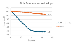
For this exercise, I have split the interval in 33 segments of 20m each.

I have calculated U using the "cylinder model":

R = 1 / 2 . Pi . ri . L . H (convection for fluid inside pipe and seawater)
R = ln(re/ri) / 2 . Pi . L . K (conduction for the pipe)
Rt = 0.000117

Then, I calculated Q using DT/Rt.

After that I used Q=m*c*dt

The result can be seen in the orange curve below.

I thought this cool down was too slow, and tried to use mass flow rate (blue curve below), because afterall the fluid in the pipe is moving.

I think it makes more sense now, but I am not sure I can simply use mass flow rate as this is Kg/second, not Kg.

I think there may be an explanation why you could use this simplification, but I don`t have that knowledge.

Excel is also attached, please have a look, if you have time.

Thank you very much for all the help and explanations so far

Igor

1734579586176.png
 

Attachments

  • heat transfer.xlsx
    337.2 KB · Views: 6
The formula works both ways.

If you want energy (Joules) then use mass

If you want energy per second (J/s or W), then use kg/sec

Just be consistant.
 
Yes the heat transfer and mass flow is on a time basis.

When I have time I will review everything from your recent posts and your spreadsheet and make comments.
 
Yes the heat transfer and mass flow is on a time basis.

When I have time I will review everything from your recent posts and your spreadsheet and make comments.

Thanks! I think if the calculations are correct, then my final question is:

For the graph above, considering each segment is 20m (as per spreadsheet), then each point of that curve is the final steady state temperature of the fluid inside the pipe flowing at the fixed rate (assumed on the spreadsheet) for T=infinity ?

I am still not sure that calculation is right...

Igor
 

Part and Inventory Search

Sponsor