powerproblems
Industrial
Good day all,
I am looking for the correct explanation of what is occurring in the parallel conductors in the report below. The conductors are (6) Parallel 500 MCM per phase with approximately 1200 amps of load on them. The pictures show the way phases are laid in the cable tray that they are laid in. I realize that the heating of these cables is related to the way the phases are arranged in the tray and that the only cure is likely laying the conductors out in ABC order.
I would really like the explanation of what is happening in this scenario.
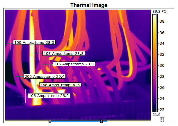
Below is an infrared image of the conductors connected at the 2500 amp feed switch located in the MDP upstairs on the mezzanine. The image shows the amp reading and temperature on the brown (Left Phase A) conductors It shows that the conductors are different temperatures, they are carrying different amounts of current even though they are parallel conductors connected to the same point and the conductors are the same length The amount of current is directly proportionate to the temperature:
[URL unfurl="true"]https://res.cloudinary.com/engineering-com/raw/upload/v1429717183/tips/2383A6EF-D06E-4815-A34B-538BDC96E6BC_hyxi6d.SNAG[/url]
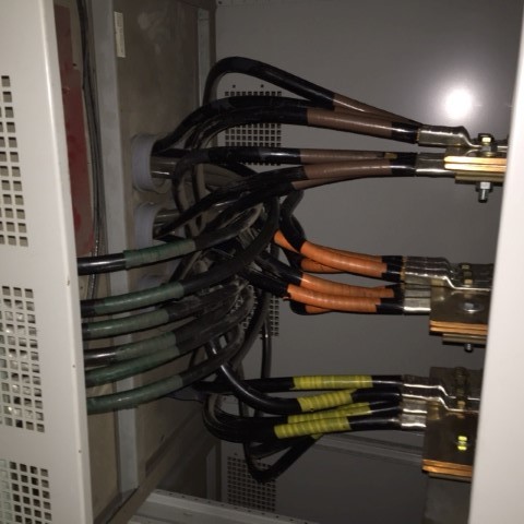
Below is a visual picture of the same conductors:

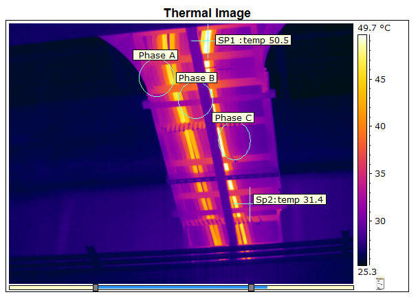
This next infrared image shows the conductors in the cable tray. This image was taken where the conductor split off the main cable tray so that all of the conductors seen in the image are the feed conductors to DS-5. I have also marked the way that the conductors are laid out in the tray by phase. On the left there are (6) 500 MCM Phase A conductors, in the middle are (6) 500MCM phase B conductors and on the right are (6) 500 MCM conductors. These conductors are the same manufacturer and all have THHN insulation. Again they are the same length connected to the same point using the same terminations.
The terminations were replaced when after this condition was first documented thinking that some of the terminations had higher resistance than others.
The temperatures are close to the temperatures recorded in the image taken at the feed switch at the MDP and stay consistent throughout the distance of the cable tray and at the terminations to the DS-5 lugs. It can clearly be seen that the conductors that are closest to the next phase are the warmest and therefore carrying more amperage the right A phase wire and the left B phase wire are next to each other and warmer, The right B phase wire and the left C phase wire are next to each other and warmer than the other conductors.
[URL unfurl="true"]https://res.cloudinary.com/engineering-com/raw/upload/v1429717386/tips/F6E6B619-0209-4DF9-84ED-D8CB1A56A7EC_cinhik.SNAG[/url][URL unfurl="true"]https://res.cloudinary.com/engineering-com/raw/upload/v1429717415/tips/2ABEA761-1A49-4788-9A20-57CD05C0AC32_ubqkad.SNAG[/url]
All of the temperatures recorded in the infrared images were in Celsius. This is so that the temperatures can be easily compared to the temperature rating of the THHN Insulation at 90⁰C. Ambient temperature in the building was approximately 24⁰C (75⁰F) at the time of this study. If the ambient temperature climbed to 35⁰C (95⁰F) the rise in the insulation would be proportionate at 60⁰C. This temperature would be more affected by the load on the rectifiers that DS-5 feeds. The rectifiers are run at higher amperage with larger parts. I cannot say what parts were being run when this survey was performed.
The image below shows where the parallel conductors enter DS-5 near the terminations. This is how we insured that the phasing in the cable tray was phased as stated above:
I am looking for the correct explanation of what is occurring in the parallel conductors in the report below. The conductors are (6) Parallel 500 MCM per phase with approximately 1200 amps of load on them. The pictures show the way phases are laid in the cable tray that they are laid in. I realize that the heating of these cables is related to the way the phases are arranged in the tray and that the only cure is likely laying the conductors out in ABC order.
I would really like the explanation of what is happening in this scenario.
Below is an infrared image of the conductors connected at the 2500 amp feed switch located in the MDP upstairs on the mezzanine. The image shows the amp reading and temperature on the brown (Left Phase A) conductors It shows that the conductors are different temperatures, they are carrying different amounts of current even though they are parallel conductors connected to the same point and the conductors are the same length The amount of current is directly proportionate to the temperature:
[URL unfurl="true"]https://res.cloudinary.com/engineering-com/raw/upload/v1429717183/tips/2383A6EF-D06E-4815-A34B-538BDC96E6BC_hyxi6d.SNAG[/url]
Below is a visual picture of the same conductors:

This next infrared image shows the conductors in the cable tray. This image was taken where the conductor split off the main cable tray so that all of the conductors seen in the image are the feed conductors to DS-5. I have also marked the way that the conductors are laid out in the tray by phase. On the left there are (6) 500 MCM Phase A conductors, in the middle are (6) 500MCM phase B conductors and on the right are (6) 500 MCM conductors. These conductors are the same manufacturer and all have THHN insulation. Again they are the same length connected to the same point using the same terminations.
The terminations were replaced when after this condition was first documented thinking that some of the terminations had higher resistance than others.
The temperatures are close to the temperatures recorded in the image taken at the feed switch at the MDP and stay consistent throughout the distance of the cable tray and at the terminations to the DS-5 lugs. It can clearly be seen that the conductors that are closest to the next phase are the warmest and therefore carrying more amperage the right A phase wire and the left B phase wire are next to each other and warmer, The right B phase wire and the left C phase wire are next to each other and warmer than the other conductors.
[URL unfurl="true"]https://res.cloudinary.com/engineering-com/raw/upload/v1429717386/tips/F6E6B619-0209-4DF9-84ED-D8CB1A56A7EC_cinhik.SNAG[/url][URL unfurl="true"]https://res.cloudinary.com/engineering-com/raw/upload/v1429717415/tips/2ABEA761-1A49-4788-9A20-57CD05C0AC32_ubqkad.SNAG[/url]
All of the temperatures recorded in the infrared images were in Celsius. This is so that the temperatures can be easily compared to the temperature rating of the THHN Insulation at 90⁰C. Ambient temperature in the building was approximately 24⁰C (75⁰F) at the time of this study. If the ambient temperature climbed to 35⁰C (95⁰F) the rise in the insulation would be proportionate at 60⁰C. This temperature would be more affected by the load on the rectifiers that DS-5 feeds. The rectifiers are run at higher amperage with larger parts. I cannot say what parts were being run when this survey was performed.
The image below shows where the parallel conductors enter DS-5 near the terminations. This is how we insured that the phasing in the cable tray was phased as stated above:


