Continue to Site

Eng-Tips is the largest engineering community on the Internet

Intelligent Work Forums for Engineering Professionals

  • Congratulations waross on being selected by the Eng-Tips community for having the most helpful posts in the forums last week. Way to Go!

Heating concrete with water/glycol. Tryinig to quantify response time based on slab thickness 3

Status
Not open for further replies.

NRNEngineer

Mechanical
Dec 17, 2021
5
I'm planning on heating a new concrete slab foundation at an industrial facility using an existing 50% water/glycol source. The purpose of the hydronic heating is for snow melt. I'm trying to calculate the time it would take to raise the surface temperature of the slab to 40deg F for a few different scenarios assuming that the entire slab is starting at 0deg F. Two scenarios I'm looking at would have the W/G tubing installed underneath 12" or 18" slabs (which would be easier to construct) and one scenario has the tubing installed within the concrete 6" beneath the surface (the deepest depth I've seen recommended in literature, which is oriented at driveway and sidewalk installations)

My problem is that this doesn't seem to be a trivial ask. It's a transient heat transfer problem involving not only the thermal properties of the concrete, but also the heat lost to the air and soil as the body begins to heat up. It's a real head-scratcher that has me cracking open my old Incropera Intro to Heat Transfer book.

If anyone could point me in the right direction I'd be very grateful. If anyone wants to take a crack at it, the details are below.

The water glycol can be assumed to be an average of 150deg F. This is a small stream tapped off of a large set of boilers so energy use is of little concern for this application.
The concrete is assumed to have a thermal conductivity, k = 0.98 BTU-ft/ft^2-F-hr
The convection to the atmosphere at the top of the slab, h = 2 BTU/hr-ft^2-F
The insulation below the slab has a R-value of 10 ft^2-F-hr/BTU

Sketch attached showing the three scenarios
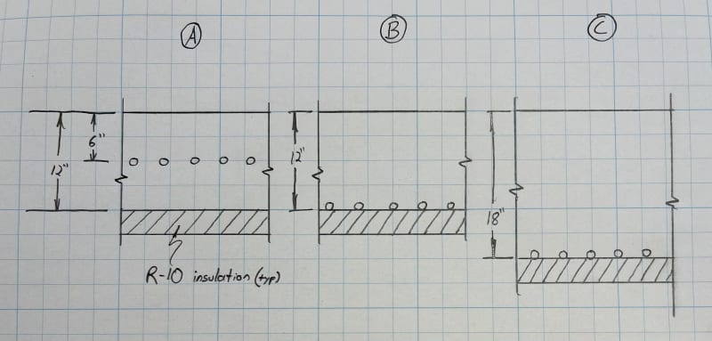
IMG_0241_rau6og.jpg


Thank You,
-NRNEngineer
 
Replies continue below

Recommended for you

You must be nearer the surface, 6" is still a very long ways.
Yes, this is a complex HT problem.
You start by solving the steady state condition, whatever your inlet temp is, the flow, 0F air, dry surface, and see if that is even possible.
That will at least give you the various heat losses in the end state.
Then you can solve by slicing this into temp steps and solving each of those.
And remember that actually melting snow or ice will take huge amounts of energy.
These systems are usually run all of the time once winter arrives.
If the slab isn't warm when it starts to snow you may never catch up.

= = = = = = = = = = = = = = = = = = = =
P.E. Metallurgy, consulting work welcomed
 
Thanks Ed, that's about what I've gathered. The slab is going to have some complex rebar which is why I'm trying to justify installing it underneath. It will have some post-installed anchors as well which require 4"+ deep holes drilled after the tubing is encased in concrete. Those are the upper-limit on tubing depth.

The steady state analysis has been done and the system has been designed to keep up with 0.5"/hr of snowfall while accounting for convection to the atmosphere and losses to the ground. Since we have a huge glycol supply it can do that pretty easily. The R-10 underneath has a much greater thermal resistance compared to concrete. So much so that ~90% of the energy is directed upwards almost no matter where the tubing goes.

I'll take a stab at slicing this into thinner bodies and trying to solve for those. A Biot number < 0.1 can be obtained if the slices are less than 0.5" thick so maybe I can approximate this using the lumped-capacitance method. Thanks
 
There are HVAC guys who do snow-melt regularly, and while I haven't looked at an ASHRAE book in a long time, I'm sure I recall seeing a section in one that talked about this type of installation.
 
If you want speed, you don't want a literal truckload of thermal resistance; you'd want the heating pipes as close to the surface as possible. As Ed suggests, sizing the piping and flow for steady state will make the system suck for transient cases, particularly if there's already ice or snow on the concrete. Snow is insulative.

TTFN (ta ta for now)
I can do absolutely anything. I'm an expert! faq731-376 forum1529 Entire Forum list
 
TBP, Thanks for the heads up. I found it in the HVAC Applications Handbook. The 1995 ed. has some good information (although nothing on transient analysis). I'm looking into ordering the latest copy.

IRstuff, Because of the post-installed anchors, the tubing can't be very close to the surface without a danger of being drilled in to. With the deeper embedment I'm trying to understand what kind of startup time the plant will have to contend with. If it's too long the system may not be worth it. I do feel confident that the system will eventually be able to melt the snow though. It's oversized and designed conservatively. Plus it's an industrial facility, not a hospital entrance, so the standards are comparatively lower.

 
What's the expected power density at the surface of the concrete in W/in^2. SAE-AIR-1168-4 has a value around 1 W/in^2 for "running wet" de-icing of aircraft windshields

TTFN (ta ta for now)
I can do absolutely anything. I'm an expert! faq731-376 forum1529 Entire Forum list
 
The calculated steady-state load was about 155 BTU/(hr*ft^2) which is 0.315 W/in^2

Is the value of 1 W/in^2 for an aircraft in flight?
 
like Ed sates, tubing near the surface is best. Reasoning: if tubing is placed far from the surface, heat transfer to surface takes longer - too much mass. However, tubing placement should not be placed in locations where penetrations into the concrete - leaks.

take a moment and read through this website:
feel free to call them and consult if desired.

good luck.
 
Raising the temp you need to know what sort of time period you are looking at.

A few years of looking at heating insulated pipelines tells me that this time period becomes you defining factor.

Too short and you need 4-5 times the power needed for steady state heat loss.

Unless your time is of the order of 5-7 days then you are at min 1.5 and worst case 5 times the steady state heat load.

You can run transient analysis using CFD and similar technology, or just use the ROT above...

Remember - More details = better answers
Also: If you get a response it's polite to respond to it.
 
Ignoring ALL ELSE, the amount of heat required to raise 6-in thick concrete is 1507 W*hr/m^2. Since there are truckloads of heat losses, this is the absolute best case, since I've ignored heat loss, thermal conductivity. etc.

slab_c6qoxw.png


TTFN (ta ta for now)
I can do absolutely anything. I'm an expert! faq731-376 forum1529 Entire Forum list
 
Why heat the concrete? All you really want to do is melt the snow and ice forming on top at the interface. Just keep the surface temperature above freezing.

If you can supply enough heat at the surface to compensate for heat lost by convection and nighttime
radiation to the air and space above and by conduction any ice and snow above when it is forming, that's the bulk of the problem solved.

The earth below will conduct its heat upwards whenever it is warmer than the surface temperature (probably always during the winter). If you try to make the entire slab warmer, you may wind up heating a bunch of that earth below. I'd consider the slab as a (rather poor) insulator and focus on keeping the top couple of inches above 32°F. The insulation below the slab will help with that assumption too. I think you said 90% goes up anyway. Placing the heating elements near the top of the slab would be the best location.

Once snow falls above, that would act as another layer of insulation and stop convection by air and radiation to space. Include those heat losses, if there can be ice without snow.

It seems that all you need to do is keep the interface of the slab and ice, or the slab and snow at 33°F. It would appear that if you can heat maybe the first 2 inches of concrete and say a a half inch of ice above it to 32°F and melt it, you could keep up with the ice forming process. You need to provide enough heat to raise the temperature of the ice above to 32°F plus the heat of fusion of 334 J per kg of ice above to melt it away, Any additional cover of ice or snow above would fall down and contact the slab as it replaces the ice that has melted. Just keep that process running.


But you already seem to have a handle on the steady state process and you want to simulate the transients. For that you need the heat capacities of concrete and ice and the masses of each that will be heated.
Concrete seems to be 880 J/kg·K, assume the thickness you want to heat at the top and calculate the mass.
Do the same for some thickness of ice at 2.108 kJ/kg·K.

Calculate the heat needed to raise the temperature from the initial temperatures of each material when you push the start button. What's the lowest temperature at which your system will start up?

The time it will take is according to the rate at which you supply that heat. Once at 33°F, steady state can be take over.

If you can provide whatever that heat is plus the heat for the steady state process, you should be able to start up and keep all the ice melting continuously thereafter. A hockey rink in reverse.
 
It seems to be a starightforward 1 dimensional problem, and should be easily modeled on modern software.
As a first approximation ,the time needed to bring the surface to 40F would vary by the square of the distance from the W/G tubes to the surface . There may be 1940's era graphs of a similar problem solved in the kreith heat transfer texts.

"...when logic, and proportion, have fallen, sloppy dead..." Grace Slick
 
Are there Heisler charts that would work for this ?

= = = = = = = = = = = = = = = = = = = =
P.E. Metallurgy, consulting work welcomed
 
NRNEngineer said:
Thanks Ed, that's about what I've gathered. The slab is going to have some complex rebar which is why I'm trying to justify installing it underneath. It will have some post-installed anchors as well which require 4"+ deep holes drilled after the tubing is encased in concrete. Those are the upper-limit on tubing depth.

None of this is out of the norm for snowmelt installations - structural slabs are built with snowmelt at 4" depth all the time.

You know where your embeds need to be ahead of time; it's as simple as not putting tubing there. 'Complex' rebar is vague, but more bar makes the tubing installation easier, not harder. Typical flatwork with mesh or bar in the bottom only means the tubing has to be tied on chairs so it won't float, which is not always trivial. If you have a top layer of bar, the tubing can go under it and it's easy to make it stay where it needs to stay.

Any experienced snow melt installer will be able to handle these restrictions without blinking; don't compromise the function of your system to solve perceived problems that aren't really problems.
 
Hi Everyone, I just wanted to post an update and thank everyone who weighed in on this thread.

We're going with a 6" maximum tubing depth. For me, that's the best tradeoff between system performance and eliminating the possibility of damage from post-installed anchors. I know some will disagree, but in this case the customer can spare the time/energy required for startup and this keeps rogue drill bits from killing the system prematurely.

User "IRStuff" above posted about calculating the "best-case" time to heat the concrete. I ran these calcs for the design conditions and came up with 1.8hr for a 6" slab, 3.8hr for a 12" slab, and 8.1hr for a 26" slab. Again, that's ignoring ALL losses, but a helpful benchmark anyway.

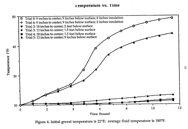
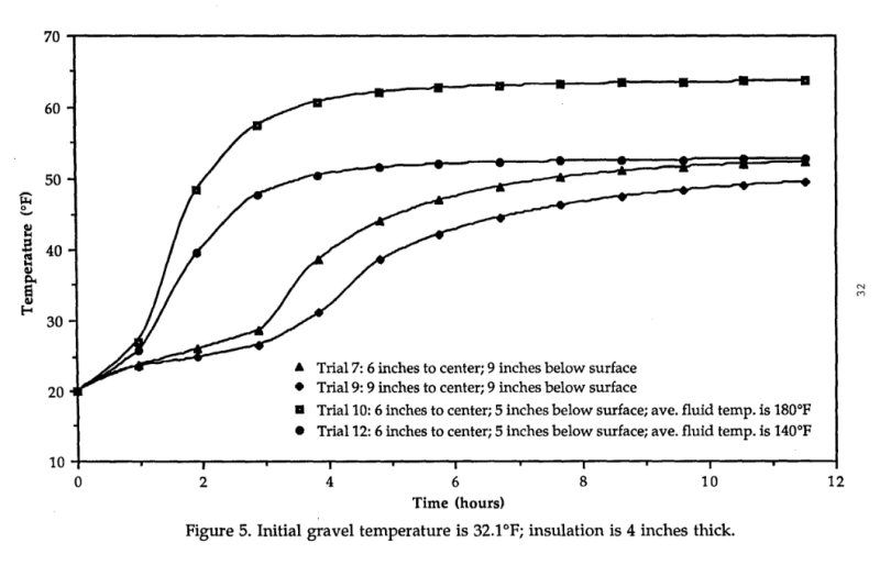
Actually calculating the transient effects was unfortunately too much of a problem for the amount of time I had to invest in this. I did, however find a 1995 Alaska DOT paper investigating hydronic heating of roadways in which they set up test rigs embedded in gravel/asphalt. I'm attaching some of the relevant graphs below which give the only decent empirical data I was able to find on the subject. The full report can be found at:
ADOT_1_uipnvk.png


ADOT_2_ybuxjw.png


I appreciate the help and knowledge. Thanks, Eng-Tipsters
 
Status
Not open for further replies.

Part and Inventory Search

Sponsor