Continue to Site

Eng-Tips is the largest engineering community on the Internet

Intelligent Work Forums for Engineering Professionals

  • Congratulations KootK on being selected by the Eng-Tips community for having the most helpful posts in the forums last week. Way to Go!

Helical Soil Anchors

Status
Not open for further replies.

Sweever

Structural
Sep 13, 2017
29
I am a structural engineer, not geotechnical, so some of my terminology may be off. I have project that involves the failure of a dry stack stone wall, approximately 9 feet high. The original drawings call for 6 helical soil anchors to stabilize an approximate 8 foot high soil elevation difference. The makeup of the wall is as follows, Sandy soil, 1x10 vertical wood planking, geotextile fabric, and then a wire mesh (though the existing conditions show a poly fabric mesh has been substituted), six soil anchors (helical with 18"x18" plate) spaced (3 approximately 2 feet down from the top of the soil and then 3 more 5 feet below the upper row), then the drystack wall.

Based on this, I would stay the drystack wall is not intended to retain soil. It should also be noted that the 1x10 wood framing is rotten (after 7 years of installation)

The upper row of soil anchors appears to have dropped approximately 3.5-4 feet lower than on the original design drawings and in two locations, the anchors appear to have pulled out 4-7" from the soil.

I have two questions,
1., is it normal to have this type of configuration to retain soil? Seems odd there is not some kind of structural wall or framing that the helical anchors tie into to retain the soil. Surely the wire mesh or poly mesh is not meant to retain the soil?
2. Would excessive rain (which happened the day before the collapse) cause the soil anchors to loose their structural integrity/capacity?

Thanks


Replies continue below

Recommended for you

Sounds to me that the soil anchors were to simulate tie backs or dead men. May not have been extended back far enough beyond the failure plane to develop the passive pressure needed. Also, the diameter of the blades may not have been large enough to develop the needed lateral resistance. This scenario is not normal in my opinion.

The 2x10’s should have been pressure treated. I used PT 2x6’s on my wall at home and they are still in good condition after 30 years.

Yes, excessive rain could contribute too.

Mike McCann, PE, SE (WA, HI)


Sounds pretty sick. If any help from us, a photo or two might help in describing the insinuation.
 
1. Would need to see a picture but doesn't sound normal.
2. Hydro-static pressure from excessive rain is likely to have caused or contributed to the collapse especially if there is no back drain present.
 
These anchors are intended for mobile home tie down anchorage ... usually 600 to 1200# capacity, and not much depth of purchase.

Mike McCann, PE, SE (WA, HI)


You might check to see if these are helical "TIES" or helical "SOIL NAILS".

I just read an article on this - the TIES are usually used with a single or double helix at the end of the system, extending back beyond the assumed soil failure plane and typically tie the dirt beyond the plane to the face of a structural wall facing.

SOIL NAILS are typically long bars or pipes with multiple smaller helixes along their length. The idea here is that the nail extends across the failure plane and ties the two sides of the soil together so that the slippage along the plane is prevented. The nails have opposite directing tension on each side of the plan and are not intended to "hold back" a structural wall. In fact, they can be used with a simple shotcrete wall system or perhaps something like what you describe.

I'm not sure what to say about the drop in the anchors or the pull out. Just found the distinction described above as possibly helpful.


How the hell are we meant to understand the configuration of the wall when you just listed a load of items and no discussion on how they are placed or connected. We need a sketch or photo.

Also, I would love to see how the "anchors" are connected to the dry stack stone wall. In my experience you would need a very large plate on the front of the wall to spread the load. Otherwise the wall will pull off the anchor.

And a dry stack stone wall should NEVER be used as a retaining wall. There is no way of really assessing its structural integrity.
 
Love the intensity EireChch.

Agree- although the details are lacking from the OP, the system sounds slap-dash.

1. This is not a normal configuration- dry stacked stone is frowned upon these days and is not a predictable building medium.
2. The anchorage zone of your soil nails should be into moisture-stable material, so no, not if the nails were designed properly...they are almost certainly too short judging by the movement described.

All the best,
Mike
 
I don't like helical tie-backs and have never seen them keep tension over time.

Yes, water is likely a problem.

Yes, settlement is likely a problem.

Unlikely that the, "Design" was fully thought out.

Not something, I'd repair in like kind.

f-d

ípapß gordo ainÆt no madre flaca!
 
Agree with most of the other respondents: doesn't sound standard or well-thought-out.
 
My apologies for the lack of details, I was running off to a site. I have attached a photo below. Some clarifications.

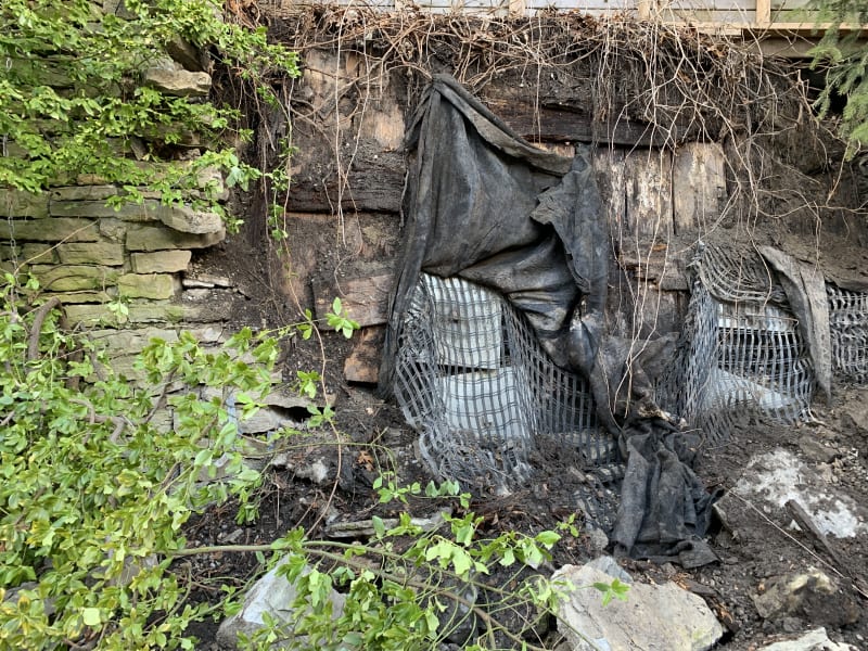
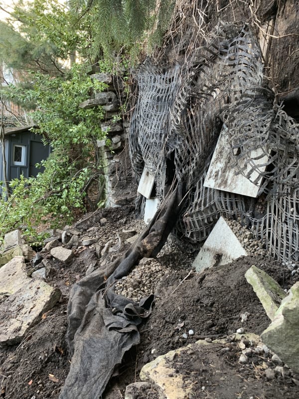
The drystack wall does not appear to be retaining in any fashion. Its just a stone wall infront of an embankment that appears to have been stabillized with helical ties/anchors. The tie backs are not attached to the stone wall in any way. See picture below which shows the metal plates for the helical anchors. You can see how they are displaced vertically and have rotated.

The configuration and order of the components of the wall is as I described above and hopefully will be more clear with the photo.

I dont know anything about the helical anchors except that they have a 18x18x3/4" plate attached to them and the drawings indicate they should be torqued to achieve the design load. No indication of minimum depth of installation

IMG_5903_v1d65j.jpg


IMG_5929_r0b3rz.jpg
 
Unfortunately, the photo doesn't help explain very much. How do you know the wall is failing? I see a pile of soil and some big rocks in front of the wall but don't see any clear evidence of wall failure. Maybe the failure is hidden behind the black fabric? Have wall movement measurements been made? Maybe the wall just looks ugly and was built ugly.

Helical anchors cannot be installed through rock without pre-drilling or coring holes. These anchors may be small diameter anchors that were installed wherever they could get the anchors in between the rocks. There may not have been any anchor displacements. The anchors may have never been installed in the locations shown on the original plans. The large 18 inch plates are used to span across any space between the rocks so that the anchors are bearing on and laterally supporting the adjacent rocks. Someone may have hung some geo-textile filter fabric and what looks like geo-grids to prevent soil from falling out from behind the rocks and through the spaces between the rocks.

it would be helpful to know if there are any inspection reports or testing reports from the anchor installation. the anchors

 
You mention having the plans available, what was the purpose of those plans? Is this just a small section that was built like this due to a previous failure, or is the entire wall constructed in this manner?
 
PEinc I don’t really understand your post. I know the wall has failed because the dry stack stone is lying on the ground in front. You can see the remaining stone wall in both pictures.

Also I mentioned in both my posts that the anchors don’t tie back the stone wall they appear to tie back the soil and the stone wall just sits out front. the way in which the soil was stabilize behind the stone wall does not make sense to me. How can 6 steel plates, poly mesh and geofabric hold back the soil?

Csigeo. Yes this was done to locally repair the wall that was bulging about 7 years ago
 
This situation reminds me of a Homeless Camp...

It looks really raunchy (fabulous new structural term here!).

I see what seems to be a structure beyond. Is there surcharge loading or trees just above the "wall", and I use the term loosely here?

Those plates look like the type used in soil nailing, but these should be combined with shotcrete and rebar, not a jumbled rock mass.

Mike McCann, PE, SE (WA, HI)


Ok so to me it looks like they tried to repair the previous failure using soil nailing and wood planks and then just matched the face of the wall without connecting anything. Were you able to see if there were large voids behind the wood planks anywhere? To me it looks like the repair may be holding but that the dry stack portion failed (probably from hydrostatic pressure from the recent rains) due to an insufficient design. It should have been shotcreted like msquared mentioned or tied in somehow.
 
Yes this is what I am saying. It appears that they are using the 1x10 vertical wood planking as their « structural wall » in which the soil nails /anchors are attached to. There is no whaler to tie this vertical wood planking together. It makes little sense structurally how they were holding back the soil and the drawings were stamped by an engineer. I didn’t know if I was missing something and if this type of soil retaining system is common.

I did not see any large voids behind the wood planking though it was difficult to see. What really stood out was how the upper soil anchors had move down 3 feet or do and that they appeared to have pulled away from direct contact with the soil Would it be unusual for a contractor to install the anchors so dimensionally off from the drawing?

Above the wall is a wooden fence and yard. There is a tree maybe 25 feet from the wall on the upper property
 
Sweever, from the photos (without blowing them up), it looks to me like some of the 18" plates are bearing against stones and or gravel. Maybe I am wrong. Maybe what looks like stone to me is actually the boards you described. I really can't tell from the photos. The gravel under the 18" plates could be packing to provide full bearing beneath the steel plates that are not parallel with or bearing directly against the stones or boards. If there are no stones remaining around the anchors, the anchors could easily have bent downward a few feet due to additional wall collapse. In any case, if I were trying to fix this "fugly" looking wall, I would consider first thickly shotcreting the front of whatever is still standing there and then, starting from near the top of the "wall," install weep holes through the shotcrete and some drilled and grouted soil nails. (Yes, these would be more expensive than helical anchors, but how have the helical worked so far?) After most of the wall is shotcreted and nailed, I would clean up some of the soil and fallen stones at the base of the wall before shotcreting and nailing the remaining, lower portion of the wall. Consider shotcreting and nailing some of the remaining, leaning stone wall to the left of the failed area. I would not use more helical anchors. I have nothing against helical anchors. I have designed them for many projects.

 
I am not trying to fix the wall, just provide an explanation as to why it failed. To me the way the original engineer tried to retain the soil was bound to fail from the start.
 
The wall primitive restraining system provided did not provide a structurally adequate interwoven global retaining matrix to constrain the soil mass for the forces seen.

"Would it be unusual for a contractor to install the anchors so dimensionally off from the drawing?" Absolutely if it was not permitted or inspected...

Mike McCann, PE, SE (WA, HI)


Status
Not open for further replies.

Part and Inventory Search

Sponsor