Continue to Site

Eng-Tips is the largest engineering community on the Internet

Intelligent Work Forums for Engineering Professionals

  • Congratulations KootK on being selected by the Eng-Tips community for having the most helpful posts in the forums last week. Way to Go!

Hello fellow engineers, I'm curr

Status
Not open for further replies.

Ramzat

Electrical
Aug 19, 2023
3
Hello fellow engineers,

I'm currently working on a wind farm generator setup where we have an earthing transformer with a capacity of 1000kVA connected to a busbar operating at a voltage level of 35kV. The Neutral Earthing Resistor (NER) has a resistance of 50.5 ohms. My objective is to determine the appropriate CT (current transformer) ratio for accurate and safe measurement and protect the bay of earthing transformer of short circuit currents in this system.
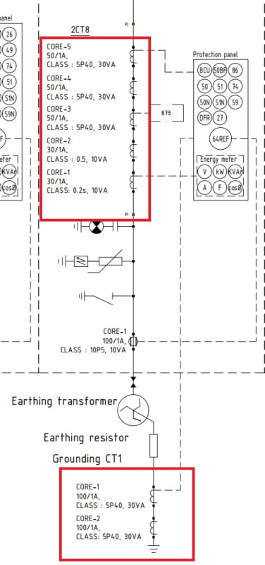
Screenshot_2023-08-19_181516_xkuiws.jpg
 
Replies continue below

Recommended for you

This is an interesting question. I'm surprised we don't have any subject matter experts chiming in to answer this. Have you found anything further out, to help you solve this?
 
Hello Tip DS,

Thank you for your response and for finding my question interesting. It seems we're still awaiting input from subject matter experts in this area. In the meantime, I've been doing some further research to better understand the considerations for selecting the CT ratio for an earthing transformer.

According to Ohm's law, if the load is 1000kVA and the voltage is 35kV, the load flow current should be 16.5 Amperes per phase. If we choose the rated current of the CT cores based on this value, we would need to select ratios like 30/1 or 50/1. However, upon reviewing other projects, I noticed that CT rated currents were sometimes chosen to be much higher than 30/1 or 50/1. In some cases, only metering cores were selected with smaller ratios like 30/1, while protection cores were chosen with ratios like 1500/1. I think there considered the short circuit current, but how? The rationale behind selecting these values for projects that are based on this approach remains unclear to me.
 
The CT ratio will depend on the transformer impedance, which is not described here, as well as the resistor size which you did list. That said I do not work with 1 amp CT's. I don't know if they are different than 5 amp CT's.
There are other parameters, like something about the system that may be needed.
You don't have any answers, because you have not provided enough information.
 
Hi cranky108,
Thank you for your responce.
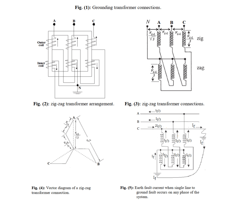
Transformer impedance is 50.5 ohm, CT rating: secondary rating in our country used 1 amp and its working principle is the same with 5 amp. When a single phase short circuit fault happens, the short circuit current in the 35kV busbar is 1400 amps, after the earthing transformer resistor, it will be 225 amps per phase. The function of earthing transformer is to reduce single phase short circuit current and to create neutral connection for 64REF relay, because in 35kV system has no neutral connection because of star delta connection step up transformer. I have attached here Earthing trasnformer drawings.
earthing_transformer_enxt1e.png
 
Ramzat - ideally, the current transformer does not saturate at the highest possible current it will see, AND it will have enough resolution for the monitoring equipment to accurately represent the current observed. What this means is that a CT intended to measure line current needs to have enough ratio that the "high" side is more than the line current (typically around 10-20%) and the "low" side fit the full-scale rating of your monitoring system (in your case, 1 amp). If the CT is intended for fault protection, it has to be capable of not saturating under fault current conditions - which are MUCH higher than normal running current conditions.

If the CT is measuring current AFTER the neutral resistor (where the current is limited to 225 A/phase), then it needs to be at least 225 A ... next "standard" rating would be suitable (i.e., 250 or 300 or whatever). But it should also result in 225 being at or near full scale on your monitor (i.e., not 1000 or 1200 or something) so that you have a noticeable "swing" between fault and no-fault conditions. Don't want the fault signal to get lost in the "noise" band of the sensor!

If the CT is BEFORE the earthing resistor, it has to be enough to handle 1400 A without saturation (next "standard" rating is 1500 or 2000). Same thing applies to low side regarding "noise".

Converting energy to motion for more than half a century
 
A CT on the neutral will see exactly the same current regardless of which side of NER it is on. Current in the circuit is the current in the circuit regardless of where in the circuit.

I’ll see your silver lining and raise you two black clouds. - Protection Operations
 
David - you are correct. No idea what I was thinking (except that I was multi-tasking at the time and may have stopped halfway through and not re-read my starting train of thought).


Converting energy to motion for more than half a century
 
Status
Not open for further replies.

Part and Inventory Search

Sponsor