Continue to Site

Eng-Tips is the largest engineering community on the Internet

Intelligent Work Forums for Engineering Professionals

  • Congratulations KootK on being selected by the Eng-Tips community for having the most helpful posts in the forums last week. Way to Go!

Hello friends, I have reached an ar

Status
Not open for further replies.

Sajjad2164

Mechanical
Dec 22, 2015
55
Hello friends, I have reached an arrangement consisting of two furnaces and thirteen return fire tubes. The general duty of the heater is 10 MW. The heater follows a natural draft circulation. I want to put four burners into each furnace to gain the task. Is it possible?
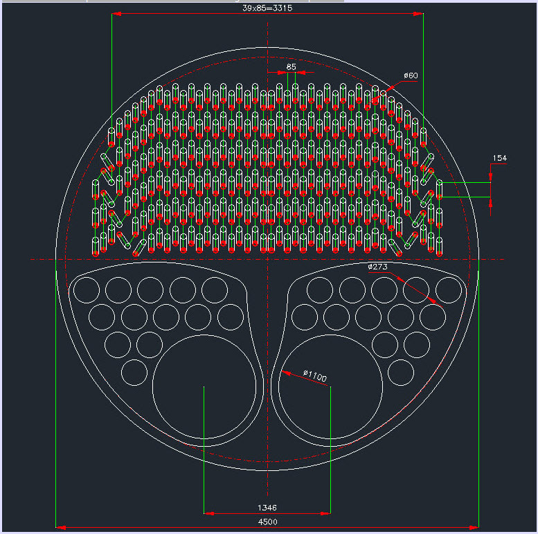
2023-05-16_13-13-51_nfxbb1.jpg
 
Replies continue below

Recommended for you

How is anyone supposed to know based on one picture and total heat of presumably 5W each heat tube?

Length of the tube?
Temperature?
Have you asked a vendor or are you the vendor?

Looks quit a lot but then this is one mother of a water bath heater.

I don't actually see much of a path for water circulation though, however I'm not a heater person.

Remember - More details = better answers
Also: If you get a response it's polite to respond to it.
 
Thanks
Code:
The length of the coils (tubes) is almost 10 m. The coils pass 12 times through the vessel.
The temperature of the crude oil passing through the coil is supposed to be from 20 to 40 degrees centigrade.
We are a vendor ourselves.
 
There is an upper limit for the heat transfer flux rate (Btu/hr/ft2 of cross sectional area) in the radiant section of the firetubes for API 12K water bath heaters that may be found in JC Campbell's Gas Conditioning and Processing, I dont remember the value now. And there is another upper limit value for the total flux rate for the entire firetube bank ( Btu/hr/ft2 per liner ft of pipe) also.
The radiant section in this case would be the 10metre first pass of the DN1100 firetubes.
 
Thanks
The fire tube consists of two parts. The first part has a 1.1 m diameter and the return tubes (or clusters) with 273 mm diameter. I used simple heat transfer equations to calculate the heat flux over the first part. I divided the first part into three segments, and the total heat flux (convection plus radiation) of every piece is as follows (the length of the straight fire tube is 9 m):
1) First part has 18033 Btu (th)/hour/square foot/F
2)Second part has 15050 Btu (th)/hour/square foot/F
And 3) Third part has 12442 Btu (th)/hour/square foot/F
 
I'm struggling to see how a vendor doesn't know all this and not be asking random strangers on an internet forum...

Is this you first attempt to design something like this?

Is there no one there to help you?

what did you do last time?

"four burners" is not a technical response. A "burner" could be any size.

Remember - More details = better answers
Also: If you get a response it's polite to respond to it.
 
These values you quote are heat transfer coefficients ( U presumably), while the design values I referred to are heat flux values. Have your values converted as required, and compare them to the values in Campbell.
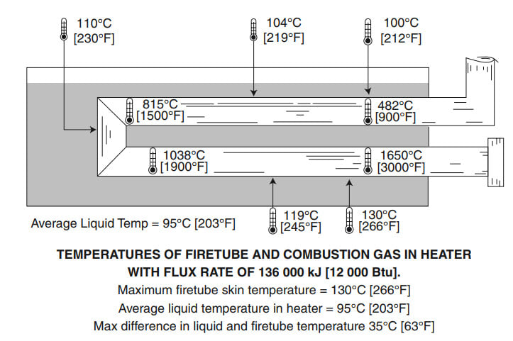
Else, you can work out if your heat flux values are acceptable by computing the OD surface temp in the first part where flux values would be highest - I would suggest keeping the surface temp at <90-95degC to prevent boiling which would otherwise lead to excessive vaporisation loss, assuming there are no constraining upper limits arising from potential scaling of the firetube OD due to dissolved Ca, Mg salts in the water.
Also check that the flame profile of the burner selected prevents flame impingement on the firetube wall, plus any other recommendations on burner location from the burner vendor. Also check that the individual main flame sensor on each burner is shielded from "seeing" the flame from the other burners for obvious reasons.
 
Code:
Take it easy!
We had been designing indirect heaters several years ago, and some calculations of those designs are left. The problem is that the people who created those designs are retired, so we need someone to go to for the issues we encounter during the design process. Another problem is that the equipment had been designed to heat natural gas, not crude oil.
I used the formulation to calculate two heat fluxes (Radiation and Convection). I used the formulation to calculate two heat fluxes (Radiation and Convection), and they are heat fluxes, not heat transfer coefficients.
2023-05-23_10-57-41_s0lva6.jpg

The limits for heat flux are articulated by API-21K as follows:
2023-05-23_11-01-30_oz49yg.jpg

The typical surface temperature is estimated by "PLP E-8-2003, Indirect Fired Heaters-2nd Ed-Rosen."
2023-05-23_11-05-55_g5lgct.jpg
 
So by the sounds of it the answers to the questions

Is this you first attempt to design something like this? - That's what is sounds like based on your reply "We had been designing indirect heaters several years ago,..."

Is there no one there to help you? - Also doesn't sound like it "The problem is that the people who created those designs are retired,...."

I don't apologise for the questions. This is not a free design consultancy here and whilst we all like to help, you come across so far as someone with no experience in designing these sort of heaters and way out of your depth.

First rule when you find yourself in a big hole is to stop digging. I would strongly recommend you find one of the retired people and offer them a months wages for a weeks work to help you out. Get this wrong and it doesn't work and you could bankrupt the company or result in a catastrophic failure which kills or injures people. It really is that bad from what we're seeing in front of us.

I'll freely admit I'm no water bath heater expert, but there doesn't look to me like anywhere near enough room for water circulation to remove heat from the fire tubes and circulate it efficiently onto the tubes. Also is this atmospheric or pressurised?


Remember - More details = better answers
Also: If you get a response it's polite to respond to it.
 
I am asked to codify the previous calculation of the company. Therefore there is nothing to be worried about. Our company will get a proper consultant for designing process, but someone in the company should be familiar with the design process, which is what I am doing here. Why are you writing these things? You cannot find a company that doesn't respect these simple rules.
The heater is an atmospheric one.
In API-12K, it is articulated that "In larger heaters, the firetube may consist of a large diameter first pass firetube and multiple return tubes manifolded into a common stack. The firetube is that portion of the firebox in contact with the heater bath.
2023-05-23_15-34-43_eigqis.jpg
 
"Our company will get a proper consultant for designing process" - Good, Then I suggest you sit down with your consultant and understand the issues from them.

I'm writing them because you didn't seem to realise how little you actually know about the design of a fired heater. Maybe you know more than you're letting on, but all we have to go on is what you put on the forum.

Remember - More details = better answers
Also: If you get a response it's polite to respond to it.
 
Friend, I do what is true.
I think struggling to know about an issue is within the forum's rules, and that's why a forum is held.
 
The formulas you've pasted across from API 12K are indeed heat flux expressions, so the values you quoted earlier should be Btu/hr/ft2 and not Btu/hr/ft2/degF.
Okay.
The first of these expressions, a modification of the Stefan Boltzmann eqn, is identical to equation 5-155 in Perry Chem Eng Handbook 7th ed, with the appropriate correction factor (1+ε1)/2 included to account for the gray firetube inside wall. While the second is the familiar Dittus-Boelter eqn. Presumably you've used correct values for each of these.
Calculations for surface temp involve iterations, you should manually check / verify some of these values, which you can do using first principles also. The overall flux values indicate it would be better to use a slightly larger surface area to keep overall flux value below 12000 btu/hr/ft2. What does API 12K or Campbell say the max skin or film temp should be for this application ?
Its been many years since I worked on these heaters, and the largest was 84inch (I vaguely recall) for NIOC, which is much smaller than this unit of 180inch dia.
Both these expressions require a value for Tcs, which can only be derived by several iterations for each section - have you verified at least a few of these values ?
Found the 2009 edn of API 12K on the internet. It states the additional upper cross sectional heat flux to be 15000 btu/hr/in2 - have you verified this for the hottest first pass at least ?
Pls note that water to be used for these heaters should be demin water, with corrosion inhibitor added for assurance.


Checking for heat flux rate based on cross sectional area:
a)DN 1100 first pass firetube = 11581btu/hr/in2 - okay
b)DN273 return pass tubes = 14460btu/hr/in2 - okay

As mentioned earlier, overall flux rate based on linear area is a bit high, pls keep overall rate below 12000btu/hr/ft2.

At the Tcs values you've quoted, for the most part, firetube OD film temp would be higher than 100degC, so heat transfer mode from the outside surface would be subcooled pool boiling, where the tube surface is blanketed by vapor bubbles, and not by natural convection in the liquid phase. Check that these Tcs values are calculated based on one of the commonly used pool boiling htc estimation methods, such as Foster Zuber (for the DN1100 section) or the Palen Small (for the close pitch DN273 return tubes). Thermal designers would not venture to do this, as long as they comply with API 12K upper limits, but it would be good to get some confirmation with these more detailed estimates.
 
Checking for linear heat flux compliance to 12K ( q<12000btu/hr/ft2):
Linear area DN1100 section = 31.1m2, DN273 section = 100.3m2, total = 1415ft2, which makes q = 12056btu/hr/ft2 - okay

It clearly looks like this heating bundle was set up to meet these 2 upper bounded heat flux limits in 12K, so the heat flux values you published earlier are probably max possible values. Which means actual Tcs profile for 10MW duty will be lower that you've published, and fuel gas demand will actually be lower than predicted by API12K (ie heater thermal eff is somewhat higher than predicted by 12K) . So I'd say there is no need for any increase in firetube surface area.
 
Thanks.
First, I assume a value for surface temperature and then use a loop that corrects the amount of Tcs each time. I will report a summary of the calculation process here.
 
Dont think I need to see these iterative calcs for Tcs. You have complied with heat flux criteria in 12K, so the rest is just icing on the cake. But as the thermal designer, you should take an interest in these detailed calcs. The mode of heat transfer from the firetube OD surface should be one of those for pool boiling, not natural convection in the liquid phase. These are iterative and laborious calcs, but you can learn a lot from this exercise.

At 95degC bulk temp, you would most likely need to install a "water saver" at the top of this heater shell, to minimise vaporisation losses.

Presume you are comfortable with the thermal design of the process crude heating bank. A good fouling factor should be used, perhaps 500btu/hr/ft2/degF, since this is presumably field wet crude oil. And some excess tubes should be included to account for tube rupture due to corrosion in the future, which would be viewed favourably by the Operating Company, and would help to swing this contract in your direction.

 
Status
Not open for further replies.

Part and Inventory Search

Sponsor