Continue to Site

Eng-Tips is the largest engineering community on the Internet

Intelligent Work Forums for Engineering Professionals

  • Congratulations KootK on being selected by the Eng-Tips community for having the most helpful posts in the forums last week. Way to Go!

Hello people! I have invented a new clean tech! Just look and ask if not understand it.

Archintrident

Civil/Environmental
Nov 19, 2024
19
WhatsApp Image 2024-11-16 at 11.50.27 AM.jpeg
This is the gravity engine.
I know, any competent engineer will immediately say that this is impossible.
He will not even look at my engine.
But I hope that you are curious enough and you will take a look.

The whole structure in the picture is immersed in water (you can use any non-viscous heavy liquid, such as mercury)
The upper level of the device is almost on the surface of the water.
The lower level is at the bottom of the water container.

The device uses the difference in water pressure on the surface of the water and at the bottom of the container.

1) The main part of the machine: A closed hermetic chain of corrugated elements.
Each corrugated element is made from a piece of corrugated hose 40 cm long in a stretched state and 10 cm in diameter. The piece of corrugated hose is hermetically sealed at both ends. There are holes in both end caps to which connecting tubes are riveted. The tubes connect the corrugated elements into a single closed, hermetic chain. Air is isolated inside the chain of corrugated elements (any gas is possible); air easily flows along the entire chain of corrugated elements, but cannot exit it.
Each corrugated element is easily compressed and stretched from 40 cm to 7 cm. I found the corrugation on Amazon, it can be compressed 7 times! This corrugation easily withstands water pressure and does not compress transversely, only longitudinally. It has a wire that prevents transverse compression.
The connecting tubes between the corrugated elements are rigid and do not change their length of 10 cm and do not compress under water pressure.

2) There are two wheels of a meter diameter.
The chain of corrugated elements is tightly wrapped around these two wheels.
- One wheel is responsible for drowning a section of the chain of corrugated elements and has a gear with a value of one.
- The second wheel is needed to raise a section of the chain of corrugated elements back to the top of the device. This wheel has a gear with a value of 3 relative to the first wheel.

The wheels are fixed in the container on axles. They can only rotate. The gears of the wheels are rigidly connected to each other by a chain, like a bicycle chain. If one wheel rotates, the other one rotates at the same time, but at a different speed.
The first wheel always rotates three times faster due to the gear ratio of 1:3.

3) A container, a little more than a meter deep. So that the wheels are sunk in water. And the chain of corrugated elements on the upper level could float on the surface of the water.

4) On the lower level of the device, right next to the first wheel, there are supporting rails. They are needed to keep the chain of corrugated elements from floating up to the lower level.

Operation of the device:

I'll start with the lower level.
The chain of corrugated elements arrives at the lower level along wheel 1. On wheel 1, the corrugated elements cannot be compressed, since the wheel has teeth (not shown in the figure) these teeth keep the corrugated elements from premature compression.
After the corrugated element leaves wheel 1, it begins to compress under the pressure of the water. Since the air leaves the corrugated element gradually, the corrugated element retains buoyancy, it is held at the lower level by the rails. The corrugated element has small wheels that slide along the rails. The rails have a slight slope in the direction of the chain movement, this reduces friction.
The slope of the rails should be minimal so that the corrugated elements do not rise high from the bottom of the tank. So as not to lose the force of water pressure.
In the direction of movement from wheel 1 to wheel 2, the corrugated containers are completely compressed.
A fully compressed corrugated element has zero buoyancy. The materials are selected so as to compensate for buoyancy to zero.
Corrugated elements with zero buoyancy are easily pulled back to the bottom and move to wheel 2.
Wheel 2 lifts the section of the corrugated chain with compressed corrugated elements to the top. There is no energy expenditure here, because there is zero buoyancy.
The corrugated elements on wheel 2 cannot be stretched, since the teeth of the wheels prevent them from stretching (the teeth are not shown in the figure).
Having risen on wheel 2 to the top of the apparatus, the compressed corrugated elements leave wheel 2 and begin to swim to wheel 1 on the surface of the water. As they move, the corrugated elements gradually stretch under the air pressure inside the chain.
The air that is currently flowing along the entire chain, squeezed out of the corrugated elements at the lower level of the apparatus.
The corrugated elements come to wheel 1 already full of air and are again sunk by wheel 1 down.

Operating principle:
Compression of the corrugated elements at the lower level by water pressure shortens the length of the section of the chain of their corrugated elements, this causes traction on both wheels.
- Since one wheel has gear 1, it wins against the wheel with gear 3. This makes wheel 2 rotate together with wheel 1, but at a speed three times slower.
- The section of the chain of corrugated elements at the lower level comes to wheel 2 compressed three times and therefore manages to rise from the lower level.
- The section of the chain of corrugated elements at the UPPER level comes to wheel 1 stretched and the faster rotating wheel 1 manages to process the faster running chain of corrugated elements. That is, it quickly drowns the corrugated elements full of air.

The calculation of the traction forces is in the figure.

Designations in the figure:

S - area of the end of the corrugated element. (minus the area of the connecting tube)
V - volume of air in the corrugated element.
0.55 kg - weight of the materials of the corrugated element.
1 m - it's depth of the water at the bottom level of the apparatus.
The gears have 3:1 values.

Also that machine already patented )
 
Replies continue below

Recommended for you

Two wheels of the same diameter are connected by a chain but turning at different speeds?

There's about 50 more obvious problems but let's start with that one
 
Two wheels of the same diameter are connected by a chain but turning at different speeds?

There's about 50 more obvious problems but let's start with that one
Because wheels have different gears 3:1And the corrugated elements chain shrinks at bottom level three times and expand back on top level.
That's why on top level chain moves faster three times and need three times faster rotating wheel to work with it.
Very looking forward for questions about another 50 problems )
 
Last edited:
If your machine has any basis in reality, you should be able to provide a simplified explanation of what it does, regardless of how complicated the process. For example, an induction motors uses a rotating magnetic field to impart motion into a rotor or a hydroelectric dam uses gravity to give a column of water potential to drive a turbine. Both are very technically complicated machines with simple explanations.

Instead you drown us with fancy sounding words that make it impossible to understand what you are thinking.
This is simply using the pressure of the water column.
The pressure compresses the chain of corrugated elements at the bottom of the apparatus.
The chain pulls both wheels, but one wheel loses and therefore the chain moves in one direction and turns both wheels.

The pressure forces exceed the buoyancy force of the air-filled corrugated elements.

That's the whole principle of operation.
 
You are pumping air to a depth of one diameter of the wheels. This will make bubbles and consume power, not generate it.


The pressure forces exceed the buoyancy force of the air-filled corrugated elements.
The figure shows the calculation.
 
I have read your description many times and I am still missing how this will move purely based on difference of buoyancy. You have a 3:1 gear ratio between wheel1 and wheel2, the wheels are equal diameter, and you have the corrugated gas chamber belt tightly stretched around the wheels, the wheel that has pockets for the collapsed corrugated chambers takes an expanded corrugated chamber into its pocket that must change shape to collapse the corrugated chamber to allow its buoyancy to reduce while the squeezed gas transfers through the corrugated chamber chain to the lower (est) pockets that now have increased buoyancy, thus they wnt to rise to the surface of the liquid and apply force to the gear 1 wheel to make it turn? And the equal sized wheels with a 3:1 ratio chain drive works with the tightly stretched corrugated chamber belt gripping each wheel's outer surface? What? How? Please explain this. I am missing the magic.
 
Last edited:
I have read your description many times and I am still missing how this will move purely based on difference of buoyancy. You have a 3:1 gear ratio between wheel1 and wheel2, the wheels are equal diameter, and you have the corrugated gas chamber belt tightly stretched around the wheels, the wheel that has pockets for the collapsed corrugated chambers takes an expanded corrugated chamber into its pocket that must change shape to collapse the corrugated chamber to allow its buoyancy to reduce while the squeezed gas transfers through the corrugated chamber chain to the lower (est) pockets that now have increased buoyancy, thus they wnt to rise to the surface of the liquid and apply force to the gear 1 wheel to make it turn? And the equal sized wheels with a 3:1 ratio chain drive works with the tightly stretched corrugated chamber belt gripping each wheel's outer surface? What? How? Please explain this. I am missing the magic.
No, it's the other way around.
The air-filled corrugated elements are pushed down to the lower level by wheel 1.
There they are compressed by pressure, generating the thrust of the apparatus.
After they are compressed, the corrugated elements go back up through wheel 2.
At the top, the air expands the corrugated elements and they are pushed down again by wheel 1 and the cycle repeats.

The essence of the difference in wheel speeds is that the chain of corrugated elements changes its length, at the lower level of the device the chain is reduced by three times in length and therefore the wheel rotating three times slower processes it calmly.

And at the top of the device the corrugated elements of the chain stretch due to filling with air and become three times longer and therefore the chain moves three times faster than the compressed one and therefore wheel 1 which rotates faster than wheel 2 manages to drown the rapidly approaching chain.
 
Last edited:
Where does the pressure come from? Pressure is a form of potential energy and takes energy to create.
The water pressure at the lower level of the apparatus is the source of pressure.
At the bottom of the device, the water presses and compresses the corrugated elements and they create the device's thrust.
 
I am missing how the buoyant chambers are 'pushed down' to be compressed. Their buoyant force is being countered by the lifting force of the expanding chambers on the other wheel? And this system will rotate? I am still missing how this will work.
 
Last edited:
So the chambers have a buoyancy ratio of 3:1. That will be cancelled out by the 1:3 gear ratio between the wheels.
Build it and see.
Another issue: The water pressure will act to compress the air in the chambers. You will have to work against water pressure to expand the chambers and fill them with air. That will take work. Energy must be expended to stretch the chambers so as to let them fill with air.
YaBut, how much energy? Exactly the same amount of energy as you recover from the rising buoyancy of the chambers, assuming 100% efficiency.
By the way, I have debunked much more subtle over-unity schemes than this one.
I applaud your efforts, misguided as they may be.
The originators of over-unity machines always manage to overlook some subtle but important detail.
In this case you have tried to use the differing buoyancy ratios, but have overlooked the torque aspect of the gear ratios, and have overlooked the energy that must be expended to fill your chambers with air.
Build it and see.
No, it's the other way around.
The air-filled corrugated elements are pushed down to the lower level by wheel 1.
There they are compressed by pressure, generating the thrust of the apparatus.
After they are compressed, the corrugated elements go back up through wheel 2.
At the top, the air expands the corrugated elements and they are pushed down again by wheel 1 and the cycle repeats.

The pressure compresses the corrugations and they pull down other air-filled corrugations!
And the pressure at the bottom of the apparatus greatly exceeds the buoyancy force of the corrugations on wheel 1.

The calculation is in the figure.
 
I think the flaw here is that the pressure and force on the lower cans is equal and opposite i.e. in both directions at the same time. Hence there is no differential force and no power to make this actually rotate.

"There they are compressed by pressure, generating the thrust of the apparatus."

You can only generate thrust if there is differential pressure or force. There isn't in this system. The pressures and forces are equal and opposite.

Also for this to work and create torque on one of your wheels, there needs to be excess work. All the energy in one wheel is matched by the energy required to make it move in the second wheel and that's assuming 100% efficiency, which doesn't exist.

So this just like taking an upside down U shaped vessel with air in it and submerging it at say 5m deep. You then have air at 0.5bar which you could release back to atmospheric pressure and create energy from a turbine. However that energy is simply the result of the energy used to push the vessel down into the water in the first place. Only if you had an endless supply of rocks and vessels could you actually release any energy. but then you would be better off sending it down to the ocean floor using a reverse bucket chain.

But back to the device - you haven't actually shown where there is excess energy and assume 100% efficiency. This thing could probably rotate if you INPUT energy into it, but you definitely won't get any out.
 
The air-filled corrugated elements are pushed down to the lower level by wheel 1.

Let's step through this one stage at a time.

Pulling buoyant things down from the surface to a lower depth requires power.

What is the power source for pulling your 'air filled corrugated elements' from the surface of the water to a depth of 1m?
 
I am missing how the buoyant chambers are 'pushed down' to be compressed. Their buoyant force is being countered by the lifting force of the expanding chambers on the other wheel? And this system will rotate? I am still missing how this will work.
The squeezing corrugated elements at the bottom of the apparatus pull both wheels towards themselves.
Because the chain of corrugated elements shortens its length under the water pressure.
Wheel 1 has a stronger gear and therefore rotates the entire apparatus towards wheel 2.
As a result, wheel 1 begins to sink the corrugated elements full of air to the bottom of the apparatus.
Then the corrugated elements come out of wheel 1 to the lower level of the apparatus and the water pressure squeezes them and the corrugated elements begin to compress and create traction, pulling in all new corrugated elements full of air.

The pressure force compressing the corrugated elements at the lower level of the apparatus is stronger than the buoyancy force of the corrugated elements full of air.
The figure shows that only three corrugated elements are full of air on wheel 1. Their buoyancy is not enough to stop the apparatus. The calculation is in the figure.
 
Let's step through this one stage at a time.

Pulling buoyant things down from the surface to a lower depth requires power.

What is the power source for pulling your 'air filled corrugated elements' from the surface of the water to a depth of 1m?
Water pressure is the power source for pulling 'air filled corrugated elements' from the surface of the water to a depth of 1m.

The squeezing corrugated elements at the bottom of the apparatus pull both wheels towards themselves.
Because the chain of corrugated elements shortens its length under the water pressure.
Wheel 1 has a stronger gear and therefore rotates the entire apparatus towards wheel 2.
As a result, wheel 1 begins to sink the corrugated elements full of air to the bottom of the apparatus.
Then the corrugated elements come out of wheel 1 to the lower level of the apparatus and the water pressure squeezes them and the corrugated elements begin to compress and create traction, pulling in all new corrugated elements full of air.

The pressure force compressing the corrugated elements at the lower level of the apparatus is stronger than the buoyancy force of the corrugated elements full of air.
The figure shows that only three corrugated elements are full of air on wheel 1. Their buoyancy is not enough to stop the apparatus. The calculation is in the figure.

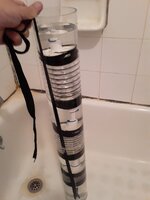
I conducted an experiment.
I took a fragment of a chain of corrugated elements and tied it to the bottom of a pipe, filled it with water.

The lower corrugated element compressed under water pressure quite reliably drowned the other two full of air corrugated elements.

This happens because the pressure of the water column is greater than the buoyancy force.
The water column is solid, and the corrugated elements have gaps between them in the form of connecting tubes.
 

Attachments

  • WhatsApp Image 2024-08-01 at 11.21.12 PM.jpeg
    WhatsApp Image 2024-08-01 at 11.21.12 PM.jpeg
    144.5 KB · Views: 7
Last edited:
I think the flaw here is that the pressure and force on the lower cans is equal and opposite i.e. in both directions at the same time. Hence there is no differential force and no power to make this actually rotate.

"There they are compressed by pressure, generating the thrust of the apparatus."

You can only generate thrust if there is differential pressure or force. There isn't in this system. The pressures and forces are equal and opposite.

Also for this to work and create torque on one of your wheels, there needs to be excess work. All the energy in one wheel is matched by the energy required to make it move in the second wheel and that's assuming 100% efficiency, which doesn't exist.

So this just like taking an upside down U shaped vessel with air in it and submerging it at say 5m deep. You then have air at 0.5bar which you could release back to atmospheric pressure and create energy from a turbine. However that energy is simply the result of the energy used to push the vessel down into the water in the first place. Only if you had an endless supply of rocks and vessels could you actually release any energy. but then you would be better off sending it down to the ocean floor using a reverse bucket chain.

But back to the device - you haven't actually shown where there is excess energy and assume 100% efficiency. This thing could probably rotate if you INPUT energy into it, but you definitely won't get any out.
The pressure force compressing the corrugated elements at the lower level of the apparatus is stronger than the buoyancy force of the corrugated elements full of air.
The figure shows that only three corrugated elements are full of air on wheel 1. Their buoyancy is not enough to stop the apparatus. The calculation is in the figure.

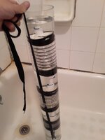
I conducted an experiment.
I took a fragment of a chain of corrugated elements and tied it to the bottom of a pipe, filled it with water.

The lower corrugated element compressed under water pressure quite reliably drowned the other two full of air corrugated elements.

This happens because the pressure of the water column is greater than the buoyancy force.
The water column is solid, and the corrugated elements have gaps between them in the form of connecting tubes.
 

Attachments

  • WhatsApp Image 2024-08-01 at 11.21.12 PM.jpeg
    WhatsApp Image 2024-08-01 at 11.21.12 PM.jpeg
    144.5 KB · Views: 6
Last edited:

Part and Inventory Search

Sponsor