Continue to Site

Eng-Tips is the largest engineering community on the Internet

Intelligent Work Forums for Engineering Professionals

  • Congratulations KootK on being selected by the Eng-Tips community for having the most helpful posts in the forums last week. Way to Go!

Hello to everybody, i have a com

Status
Not open for further replies.

thedesigner75

Automotive
Jan 6, 2023
16
Hello to everybody,

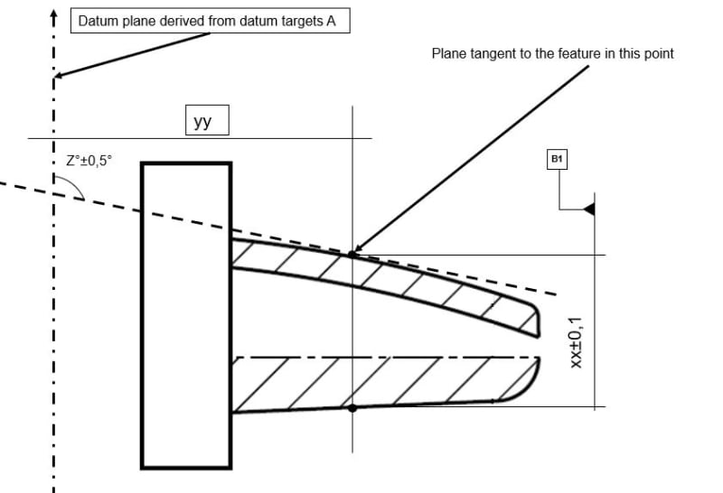
i have a complex plastic part...the strange "nose" you can see in the picture attached is used as locator (datum feature B): to qualify this datum feature i have the size dimension on B but how can i check the orientation to A? It is a complex and irregular feature without any axis to be used for orientation...then i thought to put a tangent plane in one point of the feature putting a tolerance for the angle to A...is it correct? thank you for your time and support, ciao
example_uipv3y.jpg
 
Replies continue below

Recommended for you

That's a case for a surface profile tolerance, with reference to datum feature A. If you used it on the entire "nose" you would get all the main characteristics with one control: form, size (could get rid of the +/-0.1 toleranced dimension), location (relative to datum A), and orientation (relative to datum A).
 
It appears you want to use that as a datum feature and probably at the point where it is likely to engage a slot.

The angle basic should be basic, but I caution that determining where the part touches that plane is going to be very difficult; small form changes will change the distance from [A] by a much larger amount.

Instead, I would use target lines (B1, B2) that are a [basic] distance from [A]. Each datum line would be represented by an X shaped symbol in this view. There would be no need to specify the spacing. AFAIK there is no standard means to use datum targets to establish a datum interpretation as a feature of size with a maximum material boundary so any symbolic reference is limited to a regardless of feature of size indication.
 
Thank you very much for your quick feedback...
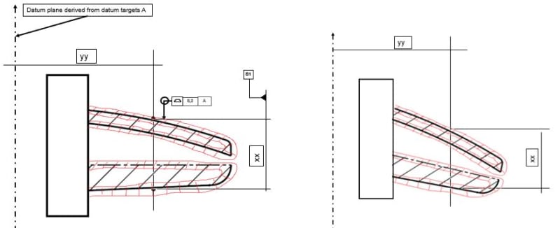
Burunduk, if i put the profile tolerance on the entire nose how can i check the orientation? because it can happen this

example-1_idt2ym.jpg


so the entire profile maybe is in target for the profile(red lines) and also for the fos (xx)...but the nose is bended...

3DDave, if i use datum targets to define secondary datum like you suggested, i still don't understand how to control orientation of the nose to datum A...

thank you!
 
Thedesigner,
The profile tolerance zone (the red lines you drew) will be at a fixed orientation (and location) relative to datum A, as shown on the left, so the bending you showed will not be allowed.
Two points to consider:

1. The true profile (theoretical exact outline) has to be defined by either basic (theoretically exact, framed) dimensions, or by the CAD model that you supply along with the drawing to the manufacturer.

2. The all-around symbol you show is only suitable for a closed shape. If the surfaces are not closed and connect to another feature (that rectangular block), the profile control should be defined with the between symbol. For example: A<->B where A and B are designated points limiting the controlled surfaces.
 
Burunduk,
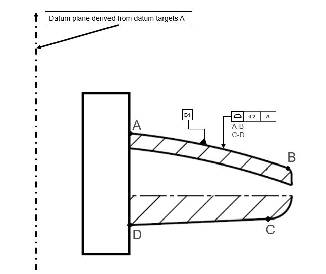
in product development today we use mainly cad models for toolmakers or inspectors...this means that we can skip all the basic dimensions info to locate tolerance zones and just to put the info about where are the datum features on the part? this means that every relation among datum features in a part is directly taken from the 3d model..this means that the drawing in this case will be like this

example3_aemlac.jpg


is it correct? thank you!
 
Since the tolerance applies in two places, and you want to keep the tolerance zones tied to each other, you have to invoke a pattern. I have a feeling you are probably working per ISO (and I'm no ISO expert) so I think the modifier you should use is CZ for common zone to connect the two. If this was an ASME drawing, I would say you should add "2X" before the feature control frame (tolerance frame) and add another leader from it to the C to D surface, because there is a standardized meaning to where the leader points when the between symbol is used.
 
And you need datum targets to define the datum feature and how to use it. A datum feature symbol placed on a curved surface like that is problematic.
 
But if the cad model is the reference why we still need to put datum targets? once we say that curved surface is datum feature B with CMM machine they can touch several points on the curved surface then the software can calculate the deviation from the cad model and check if the surface is its tolerance zone...or am i missing something?
 
thedesigner75

I'd be having a discussion with your QA management about what it is they can do for you. It's up to you to determine which features of a part are important - and you have - and it is up to you to determine how much variation the parts can have and still be usable - and you may not have; that conversation would require an analysis by the stress group with inputs from a materials engineer. Once you know those two things the QA group should be able to work with you, knowing their capabilities, to develop a plan to inspect the parts to ensure they are within the variation limits and then set tolerances to put on the drawing what those limits are. QA can also help with the presentation of the tolerance limits.

"3DDave, if i use datum targets to define secondary datum like you suggested, i still don't understand how to control orientation of the nose to datum A..."

That wasn't the question you asked. Profile tolerance is adequate.

B:

2018 Y14.5 "When a datum target area or datum target line is shown on a nonplanar surface, the shape of the datum target’s true geometric counterpart is the same as the basic shape of the surface"

ISO will likely differ.

 
Thedesigner,
Theoretically the whole curved/complex surface can be used as a datum feature, but it is more difficult to simulate a datum from it (a datum is a point/line/plane or a combination of them). Like 3DDave indicated, the shape of the "true geometric counterpart" (not sure about the ISO term) should be identical to the theoretical shape of the feature - therefore if a physical device is used to simulate the datum and constrain the part for inspection, it would need to have a surface of the inverse shape of that complex feature. Datum targets are easier because they can be simulated by pins that contact the feature at defined points or along defined lines. This would constrain the part and be used to derive datums and datum systems, which are based on theoretical planes.
 
3DDave,

the 0,2 range comes exactly from this: maximum theoretic interference (in reality we have deformation and stress) of 0,4mm between this part and its counterpart is allowed...now, if we know that the deviations come from form tolerance (the nose can be bigger or smaller in term of size) and from orientation...how to check the orientation of this complex geometry...? Burunduk wrote that the reference for all features location is the cad model so i think this could be the answer...thank you btw for your time and support [thumbsup2]
 
The profile tolerance limits the orientation as the surface is required to be within the profile tolerance limits. The zones have perfect orientation and inspection measures the deviation from those zone limits.
 
Status
Not open for further replies.

Part and Inventory Search

Sponsor