Eng-Tips is the largest engineering community on the Internet

Intelligent Work Forums for Engineering Professionals

Hello, We are currently engaged

Status
Not open for further replies.

Ariel Reyes

Civil/Environmental
Jun 21, 2018
22
0
0
PH
Hello,

We are currently engaged in the engineering design modification of an existing seawater outfall basin and outfall piping system which will convey
cooling water return effluent into the sea for discharge and dilution. Can somebody explain to me the following:

1. function of the weir within the outfall basin (see attachment 1 ).
2. ways to increase the driving head needed to overcome the high water level of 51.74 meters and the forecasted high water level of 52.25 (see attachment 2).
Do I raise the weir crest or increase the elevation of the existing seawater basin? The weir crest elevation is at 57 meters and the measured head is at
57.80 meters. Cooling water return discharge is at 45000 cubic meters per hour through a 2.6 meter diameter Bonna Pipe (reinforced concrete pipe).

Thanks in advance.
Ariel

 
 https://files.engineering.com/getfile.aspx?folder=fddbf0f9-e93f-4166-81bb-b2c6c63279a0&file=Attachment_1.pdf
Replies continue below

Recommended for you

I don't understand what has changed and why you are doing these modifications? Can you explain?

The figure MSL normally means "mane (average) Sea level. Hence what you are showing as a "rise" in seal elvel is just the maximum tidal variation.

The original design should have taken into account maximum sea level, but in reality unless your flow is increasing any rise in sea level is matched by the equal rise in the water head inside the pipe. The thing driving friction losses is the length of the pipe and the losses in those defuser pipes. Have they become blocked or subject to Marine Growth?

Anyway your questions
1 function of the weir within the outfall basin (see attachment 1 ).
The function as I see it is to maintain the incoming pipe always full of water regardless of flow. I don't know what the elevation profile of your pipe is, but my guess is that it isn't higher than 57 m. This prevents this massive pipe from seeing slug and surge type flow.


2. ways to increase the driving head needed to overcome the high water level of 51.74 meters and the forecasted high water level of 52.25 (see attachment 2).

As noted above I don't think you need it, but raising the walls is the easy solution. You need to explain more what is going on here.

Remember - More details = better answers
Also: If you get a response it's polite to respond to it.
 
Hello Little Inch,

Thanks for the reply.

The driver for these modifications is the increase in cooling water return discharge from 31000 cmh to 45000 cmh. Another thing is that from visual inspection
at 31000 cmh, there are splashes outside the basin. Must be from the jetting action of the RTR pipe.
I correct myself, this is not a rise but the maximum sea water level of 52.25 meters. The installation is relatively new and was constructed in 2013.

1. The incoming pipe centerline elevation is at 55.913. It is an RTR (reinforced thermoplastic pipe) pipe and is pressurized. The RTR pipe conveys cooling water return effluent from the heat exchangers. From your answer, may I pose another question, does the weir act as a "seal" to maintain that water. Can you please specify why it needs to maintain that water.

2. As a result of the increase in discharge from 31000 cmh to 45000 cmh, friction losses inside the pipe have increased. The invert level for the 2.6 meter diameter outfall pipe (from the basin) is 53.95 meters> From my calculations, we would need to increase the driving head to 58.6 from a 57 meter driving head to overcome the increase in headloss and a max. high water level of 52.25 meters(see attached tabulation). The 58.6 meters is the sum of 52.25m + 4.83 meters (total headloss) + 1.52 meters (from basin losses and difference in seawater and effluent densities).

Regards and Thanks
 
 https://files.engineering.com/getfile.aspx?folder=f4c88f66-3aa4-4474-8ec4-dcc6c52beaaa&file=SW_Outfall_Data.pdf
Ok, A few things which are a little strange here:

I initially got lost because in one drawing the flow is Right to left (att1) and in the second it is left to right....

If you have planned 2.44 m/sec in your 2.6m ID pipe, what sort of velocity are you getting in the 44" pipes?? (I've only just seen there are two sheets on attachment 1) Just on area that looks like 6.5 m/sec per pipe (2 off 44") - WOW

I think you're going to need a lot more than another 1.6m to prevent some splashing happening when that hits your concrete weir.

But yes the weir appears to act as a seal for the incoming pipes such that at any flow from zero to maximum, once you've filled the pipe then it remains full.

This is important because if it was allowed to drain, then on re-start you could get very high flows until the pipe fills up but also at lower flow the pipe might only be part full pipe then you can get serious slugging and surging as the flow increases until the pipe becomes full when the flowrate increases. None of those things are good.

I think your basin is now too small and you need to increase the size so that the incoming velocity can be slowed down more and allow this extra head to develop in a calmer manner.

There's too much going on here in a small space. energy is velocity squared so there's 2.1 times the energy of the incoming water to dissipate compared to now.

Any pictures of this thing in action at 31000??


Remember - More details = better answers
Also: If you get a response it's polite to respond to it.
 
Agree with LittleInch, weir is to maintain full pipe in incoming pipe. In answer to your second question, increasing the height of the walls on the basin will provide you with more driving force to overcome the losses in the discharge pipe due to the increased flow and the increase in sea level. Just need to check the hydraulics in your influent pipe back to the source to ensure that you aren't creating problems there by increasing the height of the walls.
 
Little Inch, Coloeng,

Apologies for the late reply. We just had a long discussion about this and we decided to leave the basin as it is, with 31000 cmh, except that we intend to raise the wall to another 1.6 meters and provide a 54 inch bypass line (carrying 15000 cmh) on the existing 100 inch (2.6 meter) outfall pipe (see attachment).

I've also included some pictures as requested (try to look for some close-ups).

Regards and Thanks,
Ariel
 
 https://files.engineering.com/getfile.aspx?folder=32c39e8d-4377-4571-9f3f-ba9bc4dee85a&file=NCP_Outfall_option_1.pdf
OK, that's good. That pit is certainly a boiling maelstrom of energy.
I wouldn't want to fall in!!

Some interesting corrosion on the instrument pipework and stands....

You might need some sort of mesh to stop the splashing strung below the top.

Remember - More details = better answers
Also: If you get a response it's polite to respond to it.
 
If I may ask, what sort of mesh can we use on the basin? Can't we use concrete by extending the wall by 1.6m? Can you provide a sketch?
 
I've developed a sketch for the existing outfall basin. The sketch shows a proposed 4.5 by 13 meters box culvert to which the existing 100" reinforced concrete pipe (RCP) and 56" (reinforced thermosetting resin) RTR pipe will be connected. A portion of the 100" RCP pipe will be cut to free up space on the basin and provide unimpeded flow to the RTR pipe. As shown on the sketch I've provided a sealing weir just downstream of the RTR pipe. Can anybody provide some comments on this?

Thanks,
Ariel
 
 https://files.engineering.com/getfile.aspx?folder=7d6e0f4b-a774-4451-9005-c229b8795ac2&file=SW_OUTFALL_BYPASS_LINE_OPTION_3.pdf
By mesh on the previous post I meant using the green anti wind mesh you see on agricultural building to allow air / wind through but at a much reduced rate. In your case more like the mesh grills you can get for frying pans to stop all the fat splatter., only a lot bigger and made from plastic.

Like this stuff. Maybe two layers.
Anyway I see from your previous design you've moved the new pipe upstream of the connection from the old pipe.

I think at the sort of flow and velocity you have you will get a lot of splashing and disturbance as the jet of water from your new 56" pipe hits the far wall of the pit and over time the wall may even suffer damage from the constant water jet.

I would simply mirror your existing set up, i.e. divide the current pit in two and then allow the flow to turn 90 degrees. Or maybe make it 2/3 the size to reduce the amount of splashing and agitation.

Remember - More details = better answers
Also: If you get a response it's polite to respond to it.
 
Thanks for the quick reply Little Inch, correct me if I'm mistaken, here is what I understand from your comments/suggestions:

1. Another sealing weir for the 56" RTR pipe, just a little smaller.
2. From the new sealing weir, run the RTR pipe thru a 90 degree elbow before discharging into the much reduced culvert/basin.

Please refer to attached sketch.
 
 https://files.engineering.com/getfile.aspx?folder=dfd65c20-bba1-492d-8897-ee0a3a60d1e7&file=SW_OUTFALL_BYPASS_LINE_OPTION_3A.pdf
Correct.

just my opinion of course, but its best to reduce water velocity as much as you can before trying to get the flow to turn corners.

Remember - More details = better answers
Also: If you get a response it's polite to respond to it.
 
Hello Little Inch and Everybody,

I'd like to pick up where we left off in this thread. May I ask for your technical advise on whether vents should be provided on the outfall basin (see attached sketch) and where they should be located and sized? Are there references on vent sizing.
 
 https://files.engineering.com/getfile.aspx?folder=7ec717a6-224c-4af8-a381-3b508619b4b1&file=NCP_Outfall_Basin_&_Pipe).pdf
I have just looked at this thread and offer the following observations.

(a) The boiling effect of the seawater upstream of the weir is an indication the weir has been undersized. Air could be released if flow were fast and not properly streamlined. In general one needs a stilling basin upstream of the seal weir and the existing one does not seem to have no such consideration.

(b) Answer to "function of the weir within the outfall basin" - A seal weir is always provided to control the hydraulic system. The key requirement is to ensure the discharge upto and before the seal weir is "fully submerged" to effect a full bore flow. Therefore the pump for the discharge system has a guaranteed datum to work against. This is the most efficient way of arranging a discharge. If the flow changes between an open channel and full bore flow the pump will not operating at a steady duty point, energy will be wasted and the pump degrades over time.

(c) An outfall system is always designed for the maximum sea level. The current one-year maximum of HHWL at 52.25m need to be revisited. I would find a nearby tide level gauge station and download at least the last 30 years records to get the highest possible level to check it against the local HAT and use whichever the higher.

(d) Answer to "ways to increase the driving head needed to overcome the high water level". This answer has two parts. Part 1 is water will have a level upstream of the weir determined by nature when the Froude number is 1. Nobody can change this.

weir_height_fph9hg.png


Therefore if your existing weir is unchanged the water upstream of the weir has to be around 1.5m or probably higher due to the unsteadiness without the stilling basin provision. Thereafter if the water downstream the weir never rise above the weir level then your weir is adequate. If the system is inadequate the downstream level can rise above the weir level and the weir will have to work in a submerged condition.

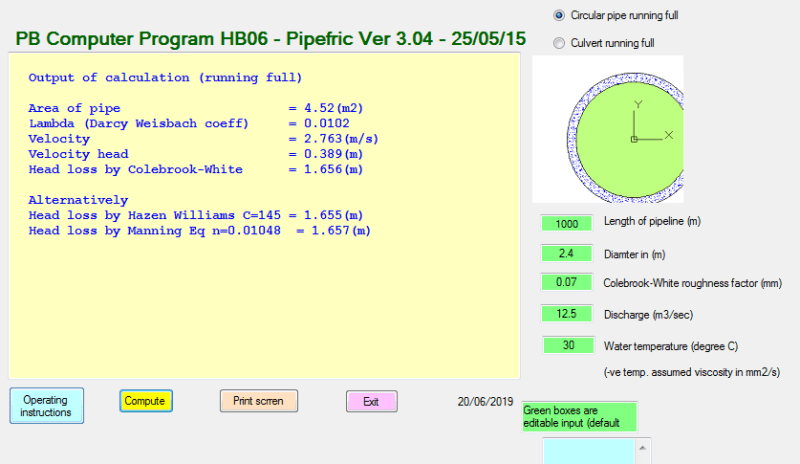
At the moment with a HHWL at 52.25 there is a head difference of 57-52.25 = 4.75m between the seal weir and the highest high water level. Whether this is enough depends on the length, profile, condition and arrangement of the 2.6m Bonna pipe. I did a quick calc assuming the 2.6m pipe has 0.1m marine growth (so the effective diameter is 2.4m) over a distance of 1km (say) without any other other secondary losses using a nominal roughness factor and got 1.6m head loss overall.

friction_head_rswtkf.png


Since the head difference is significantly higher therefore the flow in the 2.6m Bonna would be initially open channel and becomes full bore flow after passing the HHWL. Lots of air could be trapped in the 2.6m Bonna making the flow erratic and difficult to predict.

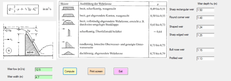
My gut feeling is the existing weir level should work for the 12.5m3/s or 45,000m/h flow.

I you raise the seal weir level you will change slightly the design of the pressurized system upstream and that can be considered if you have a submerged weir condition. However in your latest modification you now have two seal weirs and a common pit and that should improve things.

(e) Lastly regarding extending the existing pit wall my recommendation is do it with non-corrosive materials. Since there is no water to be impounded you can just erect a watertight plastic screen around the existing pit using stainless steel fixing and brackets. You can sell this idea to the owner that reducing the water spray is crucial to reduce the degradation of the surrounding infrastructure and the equipment of the plant. Visually the seal weir pit has already suffered from the chloride attack so a watertight screen, robust against the worst wind load, of at least 1.5m height above the existing pit wall can contain the seawater spray and allow remedial work to be carried out on the exposed seal weir walls.

(f) Finally I notice it is your intention to cut out a portion of the the 90-degee Bonna pipe bend to form a new common pit. It would be essentially to ensure the original pipe is not damaged and the steel liner is fully sealed afterward and if required reinforced after the modification. If the mortar inner lining of the Bonna pipe is damaged and washed away by the hydraulic action this can lead to a progressive loss of the inner lining exposing the thin steel liner to corrosion. By which time the Bonna pipe would be in danger.

My information should serve as sanity checks against your own design.

I can't answer your last question as your link does not work. Vent is provided should be for the pipeline upstream of the seal weir. Trapped compressed air is a common problem of a badly design hydraulic system.
 
Mr. Saikee119 thank you for your comments. I will attach the sketch and Civil Storm hydraulic model of the system for your review. The attached sketch is the current design w/c unfortunately does not include
a second sealing weir due to space and construction schedule limitations. There will be a common pit w/c will serve as a junction for the 100" (2.6 meter) RC Pipe and the 88" RTR Pipe w/c is pressurized.
To offset the stronger pressure from the RTR pipe (around 0.2 bar) we propose to add a 30" vent pipe. Could you comment on this and have you got references with regard to sizing the vent line.
 
 https://files.engineering.com/getfile.aspx?folder=9009a3bc-31fe-42fe-8fe0-1cb2fc0424b4&file=Node_Diagram.pdf

Ariel Reyes (Civil/Environmental)(OP)

I would suggest you to terminate the current thread and start a new one afresh because information is getting confusing as you are in the early development stage without a firm target.

I list below the modifications which all were partially conceived without a firm design. It seems you changed your mind every time you posted. This is the sure way to failure in the end.

Solution (1) - Using existing common seal weir pit by increasing the flow from 31000 to 45000m3/h but without information how the extra flow is introduced into the existing structure.
Solution (2) - Add a "flange pit" that carries the additional 15,000m3/h with its discharge joining the existing 2.6m dia discharge Bonna pipe. This scheme was indicated by a plan only without any detail.
Solution (3) - Build a separate pit to intercept the discharge (by breaking out an elbow section of the existing 2.6m discharge) and provide a separate seal weir for a new RTR pipe carrying the additional discharge.
Solution (4) - Omit the seal weir in Solution (3), move the new pit to a straight section of the existing 2.6m discharge, cover the new pit to prevent seawater splash and add an air vent.

My concern is that you are using the forum to carry out a feasibility study. Different members will offer different opinions but the worst is the ground rule was being changed from post to post. This will waste peope's time and you will get the wrong advice if the person responds does not get the full picture of your requirement.

Here is my feedback on your latest solution. Your lack of the hydraulic knowledge is a serious concern to me.

(a) If you put the new RTR pipe directly into the new common discharge pit it will not be pressurized to 0.2 bar as you expect. Nature will ensure the new common pit to have atmospheric pressure and a common water level even if you make the box airtight.
(b) The water level inside the new common pit will fluctuate in response to (but not correspond to) the daily tides and will not remain constant.
(c) Your current design is to place the new RTR pipe side by side to the existing 2.6m Bonna. Since from your own information the flow inside the Bonna will not be full bore (indicated by the hydraulic gradient). This implies the flow in the new RTR pipe will also be partially full. The consequence is the hydraulic system of the new RTR pipe will be compromised as you will not be able to know/control the head or level at the terminal end of the new RTR pipe.
(d) Your last solution will not work if the new RTR pipe is a pumped system. In such case a seal weir is needed and cam be installed inside the vented pit. If it is a gravity system with sufficient head and the the continuous movements of the interface between the full bore and open channel flow has no consequence to the system then it may work at the 15,000m3/h flow rate.

I interpret the information provided by you. Please let me know if there is any misinterpretation.
 
Status
Not open for further replies.
Back
Top