Eng-Tips is the largest engineering community on the Internet

Intelligent Work Forums for Engineering Professionals

  • Congratulations waross on being selected by the Tek-Tips community for having the most helpful posts in the forums last week. Way to Go!

HELP ALLOWABLES IN NOZZLE PUMPS!!!!! 4

Status
Not open for further replies.

J_04051988

Petroleum
Sep 6, 2023
7
0
0
ES
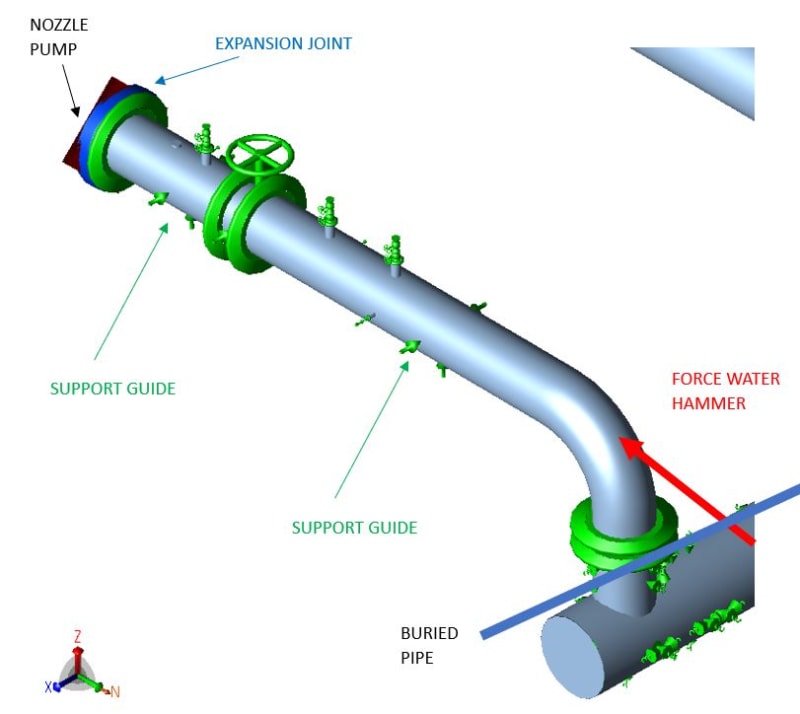
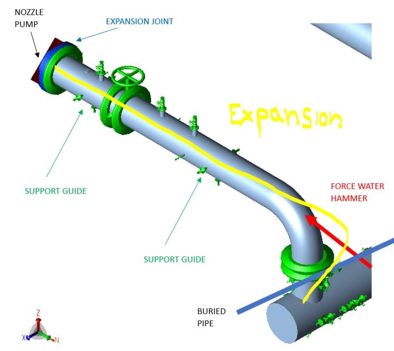
The problem is that I have low allowable values ​​for this pump. The ideal would be to put a fixed point where I indicate so that it absorbs the force of the water hammer, but it created very high stresses in the pump connection.

Captura_o5ycqg.jpg


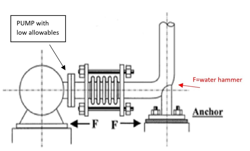
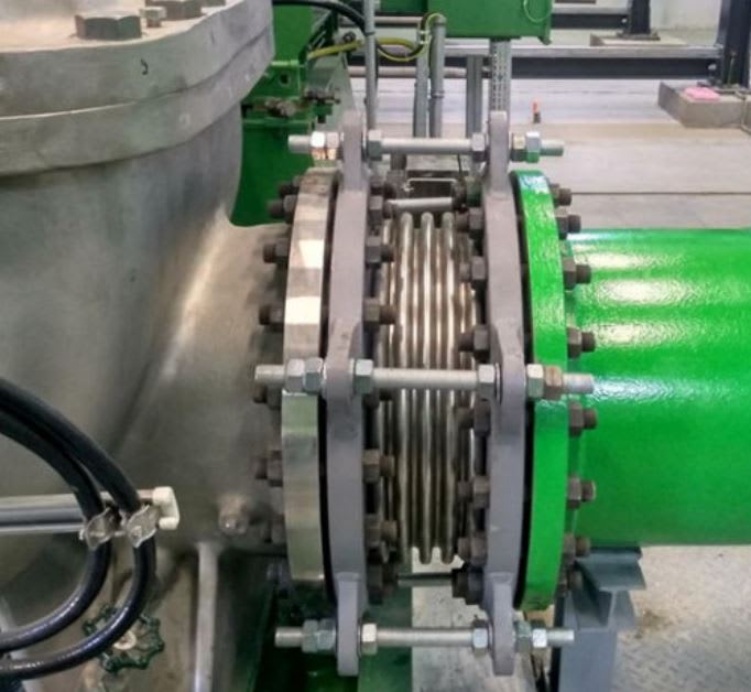
It would be correct to use an expansion joint with a double nut like the one attached in the image. On the one hand it would have the tie rods to absorb the equivalent pressure and on the other hand the inner nut to absorb the water hammer.
Captura2_kfpvt2.jpg


If I use an axial joint without tie rods I have equivalent pressure in the connection.

What could be another solution?

thank you anyway
 
Replies continue below

Recommended for you

A lot of questions:

1) What's the cause of the water hammer? A pump discharge shouldn't be hammering. Only time I've seen that is bad installs of medium consistency stock pump discharges, but your tag says Petroleum.
2) What's the temperature of the service?
3) What's the drive for an expansion joint? With it fully tied, the joint will only absorb lateral movement.
 
According to the photo, the pump appears to be on the left (unpainted).
If that is the case, is the pump supplied with properly separated liquid feed.
 
A lot of questions:

1) What's the cause of the water hammer? A pump discharge shouldn't be hammering. Only time I've seen that is bad installs of medium consistency stock pump discharges, but your tag says Petroleum.

DN 1400 pipe at 4.5 barg and 50ºC of water. The water hammer comes from the other side of the installation.

2) What's the temperature of the service?
50ºC


3) What's the drive for an expansion joint? With it fully tied, the joint will only absorb lateral movement.
I can´t transmit the equivalent pressure to the pump connection, hence the tie rods in the direction of traction and for compression (water hammer force).
For the design of the joint I have to take into account (allowable lows, forces due to water hammer, displacements in the pump)


The ideal proposal:
- Fix with anchor support for the propose of protecting the pumps in the event of a water hammer.

My problem:

A compensator is required due to the short length of the piping and minimal flexibility of pipe and components.
We are looking into using an axially constrained type, as the thermal expansion force first has to overcome the pressure thrust force before the compensator "works" i.e. compresses to accommodate thermal displacement, so It will apply a force even greater than the pressure thrust force to work on the pump nozzle.
The pipe is thermally expanding (getting longer), so the compensator must compress (get shorter).
The tie-rods will restrain the compensator against elongation due to the pressure thrust force.
For compression of the bellows the tie-rods must not work! (See the picture you sent me: the inner nuts of the tie-rods are not tightened. If the tie-rods would restrain the bellows against compression, then the compensator would be completely useless (rigid) for using here!)
The compression of the compensator only starts as soon as the force from thermal displacement is larger than the pressure thrust force (in this direction the pressure thrust force is present because the tie-rods do not work!). After that the additional spring force (Cax·∆x) of the bellows works against the pipe displacement.
All this is not a problem as long as the other end of the compensator (here the pump nozzle) can withstand the arising reaction force. However in our case this is the problem! The pump max. axial nozzle load is not high enough if the pump is fixed to the foundation.


Thank you.
 

hacksaw

According to the photo, the pump appears to be on the left (unpainted).
If that is the case, is the pump supplied with properly separated liquid feed.


Could you explain what you mean?
 
There are two issues here.

Yes in theory putting an anchor (I presume this is a 6 way anchor) causes large forces on the nozzle, mainly from thermal loads, when you stick this into a model as it assumes two absolutely rigid anchors.

What is your delta T?

Either way, this is in reality a modelling issue as the amount of deflection / movement required to make this force disappear is incredibly small if the distance between pump and support is <2m and normally taken up the inherent flexibility of the gaskets and the pump itself.

But if you don't want to go that way, then the expansion joint is Ok, but as you have two fixed anchored ends, there is no requirement for the tie rods in my opinion as there is no movement. If the elbow was a sliding support, then yes the pipe would see end cap forces due to the elbow and any potential surge so you would need to prevent the expansion joint from simply expanding, but guides and a stop would do the same thing. Anyway its a full 6 way anchor by the look of it.

But I'm with engr Paper here - sort the surge out before trying to fix the consequential issues. surge is bad for everything.

"If I use an axial joint without tie rods I have equivalent pressure in the connection." Maybe its me but I really don't understand the issue here - can you explain further what you're concerned about?

Or just bolt the pipe direct to the pump....

Remember - More details = better answers
Also: If you get a response it's polite to respond to it.
 
Your other reply came in before mine, but is this pump made from glass or something?

Remember - More details = better answers
Also: If you get a response it's polite to respond to it.
 
Well a little bit, but your buried pipe is essentially anchored no?

I still can't see why your expansion joint, if you really want one, needs any tie rods as there is basically no movement of the pipe.

The pump must be able to take some loads....

Metallic bellows reduce forces caused by expansion, but don't eliminate them. Only something like a flexible pipe will do that.

Remember - More details = better answers
Also: If you get a response it's polite to respond to it.
 
Littleinch

Yes, the buried pipe can be considered an anchor

the pump has displacements (possibly settlements) and vibrations, that's why we put the expansion joint.
On the other hand we also have a reaction in the nozzle due to the expansion


Captura4_ei0swf.jpg


Thanks for you reply.
 

So you have single phase flow of pumped liquid, water hammer occurs when a valve closes abuptly.

Have you sorted out the source of the hammering events.


Pump base settlement? Really??

Anyway still don't need tie bars. IMHO.

Remember - More details = better answers
Also: If you get a response it's polite to respond to it.
 
IMO, if for serious vibration and/or settlement issues of the pump, it may need to be other proper solution to deal with it.
By looking at the picture, the expansion joint has no axial movement allowance as the "limit rods" are tightened with three nuts on each ends without any gap.
If any consideration for using the rubber type of the expansion joint, instead of the metallic for the "water" service?
 
The picture I think was just an example.

1400NPS and 4.5 bar is HUGE.

Forces firm any surge event will be massive.

There seems to be a lot wrong here that an expansion fitting won't solve....

Remember - More details = better answers
Also: If you get a response it's polite to respond to it.
 
1) You need to work on eliminating all anchors close to a pump.
"We have a large anchor force due to the expansion."
NO YOU DO NOT. Your thinking is REVERSE logic.
For pipe stress work, you need to think like this.
YOU (or someone) PUT IN AN ANCHOR, SO IT WAS THAT ANCHOR THAT MADE THE LARGE EXPANSION FORCE.

Every time you add a support or anchor, you convert movement into force and the net pipe stress goes up. The best you can do with anchors is to move the force somewhere else. You will never decrease net stress by adding anchors, especially near a pump.
If its a vertical load problem, provide a y support and a slide in x,z plane.
2) You should try to eliminate high surge pressures.
Slow the valves down, and/or
provide a proper surge relief system.
Increase pipe diameter, or otherwise slow the fluid down.


--Einstein gave the same test to students every year. When asked why he would do something like that, "Because the answers had changed."
 
All good suggestions above. Another thing to consider is that on installations like this, you need to model the pressure thrust of the joint more precisely. The following comments are neglecting things like the joint spring rate and such. For an untied joint installed on equipment like this, the piping side of the joint will see the full pressure thrust of the joint between the flanges and the downstream elbow but the equipment side of the joint (at the flange!) will only see the additional load of the annular effective area (effective area minus inner area of the pipe). This is because the inner area of the pipe is reacted against by the equipment internals down to the foundation, rather than through the flange, casing, then the foundation. So when you are marginal on FLANGE allowables, you need to make sure you are looking at FLANGE forces.
 
Water hammer exists, there is a calculation that indicates it.

In this case I have three forces water hammer, expansion and pressure thrust.

My question is if there is a way to not transmit the forces of the water hammer to the pump nozzle?

thanks to all of you
 
Status
Not open for further replies.
Back
Top