Continue to Site

Eng-Tips is the largest engineering community on the Internet

Intelligent Work Forums for Engineering Professionals

  • Congratulations KootK on being selected by the Eng-Tips community for having the most helpful posts in the forums last week. Way to Go!

HELP ALLOWABLES IN NOZZLE PUMPS!!!!! 4

Status
Not open for further replies.

J_04051988

Petroleum
Sep 6, 2023
7
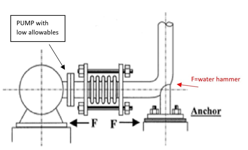
The problem is that I have low allowable values ​​for this pump. The ideal would be to put a fixed point where I indicate so that it absorbs the force of the water hammer, but it created very high stresses in the pump connection.
Captura_o5ycqg.jpg


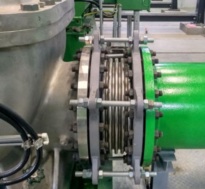
It would be correct to use an expansion joint with a double nut like the one attached in the image. On the one hand it would have the tie rods to absorb the equivalent pressure and on the other hand the inner nut to absorb the water hammer.
Captura2_kfpvt2.jpg


If I use an axial joint without tie rods I have equivalent pressure in the connection.

What could be another solution?

thank you anyway
 
Replies continue below

Recommended for you

Its difficult to avoid. Turning off the valve will stop the water hammer pressure from reaching the pump, but will not stop waterhammer force. Even if you turn off the discharge valve, waterhammer forces hit the valve and will be transferred to the pipe, then to the pump.

Waterhammer can only be stopped by hydraulic mitigation techniques. Waterhammer problems cannot be solved by pipe stress. Closing a valve cannot stop the pressure thrust from reaching the pump for the same reason, unless the valve is well anchored, but you already know that anchors near the pump do not work. You need a more flexible pipe connection configuration. It is also just treating the symptoms of the waterhammer problem. It's not doing anything to stop it.


--Einstein gave the same test to students every year. When asked why he would do something like that, "Because the answers had changed."
 
I would not put an anchor where the pump branch line connects to the header as you show in your original post. This is because this will fcrce the thermal expansion into the expansion joint which will unload the tie-rods and then the pressure thrust will be felt by both the piping to one side and the pump to the other. I don't think the pump is designed to take this pressure thrust of about 161,000 pounds but you can check with the manufacturer. An option would be to put an anchor before the pump to absorb this force but this would require a quite large anchor for this force.

Therefore I would look for a way to make the thermal expansion go in a direction away from the pump. In order to accomplish this you would need to make the piping connection to the header more flexible. As it is the connection is very stiff and the buried pipe header forms basically a partial anchor which will force the thermal expansion towards the pump. I would look at putting an offset at the connection of the pump branch to the header. Instead of going straight to the header I will turn the branch parallel with the header with an elbow in horizontal then put some straight length then elbow down. This may add enough flexibility so that if all the thermal expansion is directed towards the header the stresses in the piping at the header will be within limits.

I would keep the expansion joint with tie-rods at the connection to the pump. This will handle settling of the foundation that you are concerned with. It will also insure that no axial thermal loads are transfered to the pump. When the straight pipe expands thermally it will want to compress the expansion joint. If the piping at the header connection point is flexible enough, instead of compressing the expansion joint the pressure thrust will cause the increase in lenght of the pipe to thermal expansion to be pushed towards the header connection so no themal loads will be transfered to the pump nozzle.

So this solves both thermal expansion and settlement of the pump foundation and only thing remaining is the water hammer. For the water hammer force you cannot install any anchor or stop that will have and effect on thermal expansion. So I would check putting a axial limit stop just a couple of feet away from the expansion joint to the opposite side of the pump. The watter hammmer force I assume is directed into the downstream elbow away from the pumps so the stop would need to prevent the pump straight branch from moving towards the header connection away from the pump. The stop element attachhed to the pipe will make contact with a structural element on foundation that prevents the line from moving towards the header if a water hammer force is present but allows thermal expansion towards the header and away from the pump.

I would make the structural restricting element contacting the stop without gap and such that it is a little flexible. The piping on the pump side of the stop will want to thermally expand into the pump which will be only a couple of hundreths of an inch but this can be taken up by the stop of the line stop being a little flexible which will allow pressure thrust acting away from pump to pull any very small expansion towards pump back away from the pump if the stop was a little flexible. In other words I would not make stop of a attachment to the pipe butted directly against a concrete foundation that has no flexibility. I would butt the stop against a flexible structural element that is then attached to a concrete foundation.
 
Right. No basically straight run hitting a hugediameter, buried header, square on just will never work.
Need a big 20ft vertical loop perpendicular to the header for another 20ft, drop down and a 90° turn running parallel to the header for 20-40ft another 90 and 20-40ft into the pump. Then Eliminate the expansion joint.


--Einstein gave the same test to students every year. When asked why he would do something like that, "Because the answers had changed."
 
1503-44

I am thinking this may be the suction line but I am not sure. If so I was thinking that the line would be straight as is all the way to the header location but instead of turning straight down you would put a horizontal elbow and run straight parallel above the below groud pipe for enough distance so to satisfy stress requirements, then go down.

I think the OP needs the expansion joint anyways at the pump for settlement. If not may be able to get rid of if make the header connection piping very flexible but I believe in this case all supports would need teflon sliding pads to reduce friction load going back into the pump nozzle.
 
I've always managed to avoid expansion joints. Never used even one in 40yrs. But I always provide pipe flexibility, so I never needed one. The proposed arrangement arrangement has absolutely none. A price will be extracted...many times over.

--Einstein gave the same test to students every year. When asked why he would do something like that, "Because the answers had changed."
 
OP has two main issues - the water hammer and the thermal load on the pump flange.
Snickster had suggested providing flexibility to the pump suction line. I would look into possibility of adding a 'Surge Relief System' to protect it from the water hammer transient load. Emerson may help on this.
The main is a massive 56 Inch pipeline.

GDD
Canada
 
GD2-
Where did you dig up the pipe size?
Perhaps you can add the pimp design too.
 
hacksaw in OP second post he gave this and other design information.
 
Water temperature is only 50°C. Not like its a very high temp as things usually go, so I suggest it is a misplaced anchor problem rather then a big thermal issue. If there was some flexibility, that problem would quickly disappear.

--Einstein gave the same test to students every year. When asked why he would do something like that, "Because the answers had changed."
 
I would further add, if the water hammer issue is not resolved, the main can shift even if it is buried (see the deadend right after the branch connection) dislocating the branch with probability of flange leak and consequent impact on the pump flange.

GDD
Canada
 
hacksaw (Mechanical)8 Sep 23 20:24
GD2-
Where did you dig up the pipe size?
Perhaps you can add the pimp design too.

Hacksaw, did you find the information or do you need more time? BTW, what is a Pimp Design? It is not a funny forum. Is it?

GDD
Canada
 
GD2: Yes indeed, thanks,

The OP must be using a vertical pump for that size piping.
 
Status
Not open for further replies.

Part and Inventory Search

Sponsor