Continue to Site

Eng-Tips is the largest engineering community on the Internet

Intelligent Work Forums for Engineering Professionals

  • Congratulations KootK on being selected by the Eng-Tips community for having the most helpful posts in the forums last week. Way to Go!

Help for basic modelling

Status
Not open for further replies.

sushi75

New member
Mar 11, 2015
84
Hello!

(I have originally created this thread in the fea forum, but as I'm working with femap, it might be more relevant to post in this forum)

I'm fairly new on the wonderful world of FEA, and I'm having a bit of hard time. Based on a simple example, a tension plate with a hole, I struggle and wonder if I really got the essence of FE... sad(

I really want to have a clear idea of the problem (the statement rubbish in, rubbish out makes sense now!)

You can see attached an illustration of the model with Femap.

Basically, I modeled 1/4 of the structure (symmetry), and what I try to is to have a refine mesh near the hole.
So I have created additional curves defining the surfaces where the mesh will be refined.

If I create several surfaces, individually meshed, I have pretty much the meshing I want, but it's like having several surfaces "disconnected" so it doesn't really represent the structure.

If I just have 1 surface with curves on it, and I create nodes on these curves, when meshing the surface, the nodes created on the diagonal are ignored (see in picture where the QUAD are not connecting the nodes created on the curve).

Thus, I think I misunderstood the art of modeling...so any help is more than welcome!

Hope this was clear enough, if not don't hesitate to ask for clarifications.

Massive thanks in advance!!

Tom
 
 http://files.engineering.com/getfile.aspx?folder=1df915ac-e04e-47b4-98f9-bb99c7966674&file=plate_mesh.png
Replies continue below

Recommended for you

no, if you mesh the curves and put elements on them, you get rods/beams.

but you can mesh the curves That belong to (define) the quad, then put elements on the quad.

maybe read the user manual, and do the tutorials.

also, if you mesh all the quads at the same time (same operation) then they should understand their relationship with each other.

be aware ... if you create a quad from 4 points, or 4 curves, FeMap creates another set of curves that belong to the quad; and you have to mesh these to mesh the quad.

another day in paradise, or is paradise one day closer ?
 
Thanks rb1957 for this quick reply.

I tried to find tutorials on line for femap, but did not manage to get any. Do you know where I could find that? I'll be more than happy to have some training material to start with, would be a good way to be more familiar with the software :)

Cheers,

Tom
 
To illustrate the misunderstanding, I have modeled a 1/4 plate with a hole, fixed along the x axis and a vertical force on the opposite edge.

I created 2 surfaces separated by the diagonal. Thus I meshed each surface with quad elements.

Simple problem, but looking at the analysis result, looks like there is a discontinuity along the middle curve.

So if I have a surface I want to mesh and create curves on it to define areas with a more refine mesh, I feel like it will be wrong...

I'm a bit confused and lost!!

Thanks for your help

Tom
 
 http://files.engineering.com/getfile.aspx?folder=78cff483-a919-4a05-9dc7-3d95ce0f224d&file=model.png
there's obviously all sorts of things going on in your simple model. it seems odd that the deflected shape is consistent across the boundary but the stresses look "inconsistent". Overall the shape is deflecting the way I'd expect, you don't have symmetry 'cause you haven't restrained the Y-edge of the plate. What stress are we looking at ? (von mises, max principal, yy)

I'd step back and work through some of the tutorials.

another day in paradise, or is paradise one day closer ?
 
Hi rb1957?

On the example shown in the picture, the xx stresses are displayed and the defromed shape represents the total displacement. It looks like there is an artifical discontinuity along the curve.

I have found a lot of Patran tutorials on line, but nothing for Femap. I could still try to use that as a training material unless you know where I could find specific femap training course.

Thanks!
 
Dear Tom,
1.- Create the surface with hole,make sure you have only ONE surface.
2.- Draw the curves you like on top the surface to make divisions.
3.- Split the surface by the curves using command "Geometry > Curve - From Surface > Project". This command projects curves onto selected surfaces. You must first select the surfaces, and then select the curve(s) which you want project. FEMAP will automatically project the curves onto the selected surfaces. This command will automat­ically project normal to the surface. This command is very useful for imprinting one surface with the curves you selected. Please note you will have a few surfaces, yes, but only ONE body, a sheet body, all belongs to the same sheet body.
4.- Next use "Mesh > Mesh Control > Approach On Surface" and select all imprinted surfaces and choose "Mapped - Four Corner".
5.- Next prescribe an element size (enter a reasonable value!!) in all surfaces of the body, FEMAP will prescribe the element size in all curves in the surfaces. Use command "Mesh > Mesh Control > Size on Surface"
6.- And almost finally: use "Mesh > Mesh Control > Attributes on Surface", select all surfaces and assign the material & element type to the geometry.
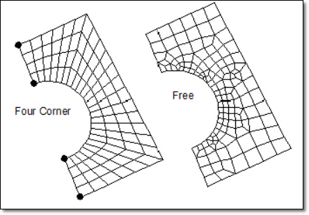
7.- And now mesh the surface geometry using "Mesh > Geometry > Surfaces", hopefuly you will have a pretty mapped mesh like this thanks to the "Four-Corner Mappe Mesh" meshing approach:

mapped-four-corner_t8yzrg.png


Good luck!.
Best regards,
Blas.

~~~~~~~~~~~~~~~~~~~~~~
Blas Molero Hidalgo
Ingeniero Industrial
Director

IBERISA
48004 BILBAO (SPAIN)
WEB: Blog de FEMAP & NX Nastran:
 
stress xx can be very misleading ... as the element x-direction doesn't need to align, unless you take care to do this ...

what does max principal look like ?

this is a pretty basis issue, which suggests going through the tutorials will help understand the s/ware.

another day in paradise, or is paradise one day closer ?
 
Blas,

I should say "muchas gracias!" This is very useful information, I think the issue I had was to grasp to idea of "body", in this case the surface, on which it can be projected curved to be meshed in order to refine the meshing.

However, when projecting the curve onto the bondary surface I have an error message from femap. It says that it cannot perform the projection as the surface should be from a solid. I don't if it's because I use a trial version for the moment, which has a lot of limitations.
Unless I did something wrong? Any idea?
I wish my spanish was better, as your site is a gold mine!!

Rb1957, indeed the Von Mises stresses look fine, at least not discontinuous. What do you mean by xx stresses could be misleading? is t because it's on the element coordinate

Thanks everyone for your help!!
Cheers
Tom
 
Dear Tom,

When you create a boundary surface or a composite curve you can not perform some geometric operations anymore like project curves, split curves...
So if this is the case for you, then you have to convert the boundary surface to a "normal" one by using Geometry / Surface / Convert.
Project your diagonal curve and you will be able to mesh it properly as Blas suggested to you.

Regards,

Seif Eddine Naffoussi, Stress Engineer
33650 Martillac û France
 
yes, stress xx is in the element orientation ... ok for very simple models (all rectangular elements). that fact that displacements looked ok (continuous across the junction) made me think things were ok.

again, I think you should take a step back and learn a bit more about the tool you're using (tutorial exercises, texts, online courses) before continuing. just building a model and looking at the pictures really isn't a good, firm, foundation.

another day in paradise, or is paradise one day closer ?
 
Thanks chaps for all your support!!

I converted the boundary surface (created from 5 curves) into 1 parametric one, and then projected the curves on which I wanted nodes on.

And it works! finally it starts making sense:))

So what is the reason exactly why femap cannot handle bondary surface?

Blas, I'll post the model so that you can see what it looks like!

I use to work with Patran, but for my next job I will be using femap, so that's why I need to get more familiar with the software!
From the first impression, femap seems more user friendly than Patran.

So if anyone knows where I can get tutorials and training material for femsp I will be happy to use that!

Cheers,

Tom
 
In the femap folder, there is a sub folder called "examples". That helps. Also, there are numerous tutorials and examples to be found on Youtube. Some are excellent.
 
Hi,

Thanks for the tip, I already noticed this functionality but as I'm using a demo version some features cannot be used and the access to the training pack is denied.

Unless anyone can provide some files I have no possibility yet to work out the examples supplied with the software.

Having some training material would be definitively beneficial😀

have a great week end,

Tom
 
Hi,

To answer BlasMolero's query, see attached a screengrab of the model I struggled with. The intention was simply to create an area with a refine mesh, defining a specific mesh control along those curves.

Thanks to all your valuable comments it works now!

The key point was to convert the boundary surface into a paramteric one, and then project the curves on this new surface.

Thanks again!

Tom
 
 http://files.engineering.com/getfile.aspx?folder=c91a5225-243a-408a-b8bc-377060e965f5&file=modelok.png
Dear Tom,
This is a free mesh. Remember: use Mesh > Mesh Control > Aproach on Surface > Mapped Four Corner and select all surfaces. Next Mesh > Mesh Control > Size on Surface and next remesh your model, you will arrive to a beautiful "mapped" mesh!.
Best regards,
Blas.

~~~~~~~~~~~~~~~~~~~~~~
Blas Molero Hidalgo
Ingeniero Industrial
Director

IBERISA
48004 BILBAO (SPAIN)
WEB: Blog de FEMAP & NX Nastran:
 
have you tried youtube ... seems to have videos to suit every situation ?

IMHO the precise mesh element paving is an intellectual exercise and shouldn't have much impact on the results.

of course, a fine mesh should give better answers than a coarse one.

IMHO, a triangle mesh is to be avoided. It might be tolerable if you add mid-side nodes.

another day in paradise, or is paradise one day closer ?
 
For tutorials, have you tried those built in to Femap? They're only quasi-tutorials, but may be helpful. Go to: Help menu; examples.
 
Status
Not open for further replies.

Part and Inventory Search

Sponsor