Eng-Tips is the largest engineering community on the Internet

Intelligent Work Forums for Engineering Professionals

Help identifying circuit. 1

Status
Not open for further replies.

bteddy1

Electrical
Apr 8, 2017
10
0
0
US
Hello,
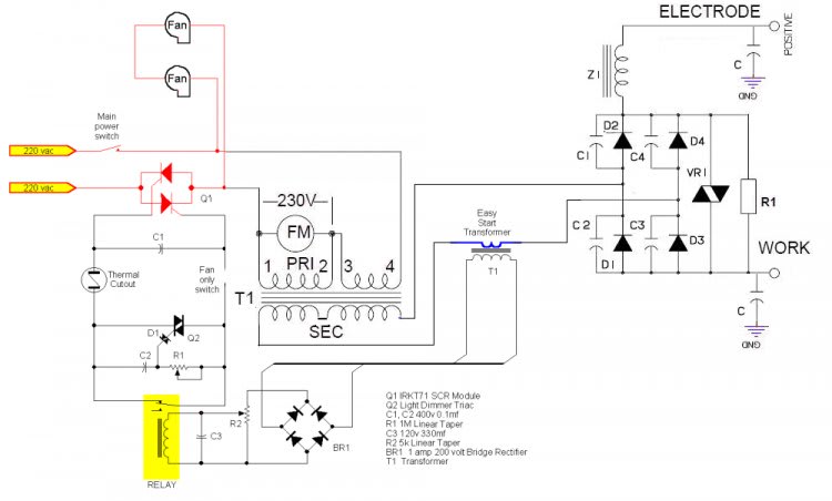
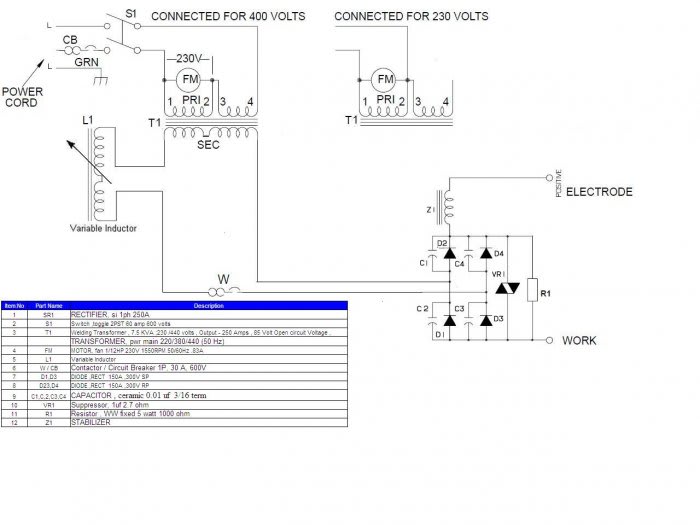
I need a little help. In reference to the circuit in the image below.
Secondary is 100V, 200A.

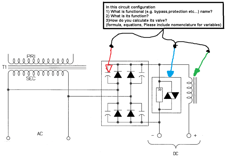
1). The capacitor in parallel with the diode in the bridge rectifier.
a). What is its functional name, how do I look it up on the web?
b). What is its purpose?
c). How do I calculate its value/specs?

2). The diac in parallel with the resistor in parallel with the bridge rectifier.
a). What is its functional name, how do I look it up on the web?
b). What is its purpose?
c). How do I calculate its value/specs?

3). The reactor (inductor) in series with the pos(+) output.
a). What is its functional name, how do I look it up on the web?
b). Its purpose is to limit inrush current and maybe filter/smooth ripples?
c). How do I calculate its value/specs?

Thanks for the assist.


Circuit_baelve.png
 
Replies continue below

Recommended for you

We do not do school work here.

If not school - why do you need to know all these things? Give us an explanation and we will help you. BTW, the text "valve" should probably read "value".

Red Arrow Component may surprise you. We don't see those so often in today's Circuits. Diodes don't have much I[sub]RR[/sub] any more.

Gunnar Englund
--------------------------------------
Half full - Half empty? I don't mind. It's what in it that counts.
 
Red = Capacitors. Not sure what their purpose is in this circuit.

Blue = Unclear in this particular circuit either. Often used to discharge capacitors when de-powered. Not sure what the Diac is doing (if that's what it really is).

Green = A reactor that is there to smooth the output (considerably)

Keith Cress
kcress -
 
Red - Snubbers. More commonly a series resistor-capacitor network, typically 100nF + 100[Ω] or so.

Blue - Probably a thyristor. The resistor is there to allow a small current to bleed through, the thyristor regulates the main current path through phase angle control.

Green - as Keith says.
 
Thank You for the responses.

No, it is not homework.
No, it is not from a text book.
It is from an owner's manual form the late 60's to early 70's.

I am trying to restore the unit and need to understand what it is.
OEM parts are not available and the parts are not marked.

And as Skogsgurra stated, "Red Arrow Component may surprise you. We don't see those so often in today's Circuits."
Now try looking it up online with out knowing what it was called or its function in the circuit.

That's is why I am asking for math, formulas, equations etc...
To come up with something as good or better.

Thanks again

Circuit_c0p9pl.png
 
OK "Honest Ted"

The red ones first: Diodes used to have terrible reverse recovery currents back in the sixties. And when the Carriers were used up, the current ended very abruptly and caused lots of HF emission. That didn't cause much problems in industrial Equipment but was a big problem in AM radios and also TV sets. So the capacitors were added to reduce EMI (radio interference). You do not need them today.

The Diac, if it is one, could also be a TVS of some other kind, is a transient protection that was sometimes needed back in the Days when rectifiers were not as overvoltage tolerant as they are today. Use a suitable varistor (MOV) instead. Much better.

The choke is there to even out current pulsations caused by the full-wave rectifier. I don't know if you actually need smooth CURRENT, but if you need that use a choke with same Fe area and same winding. If you, which is way more common, need a smooth VOLTAGE, then ditch the choke and use a capacitor, electrolytic, of suitable size. Remember to use a capacitor with at least 200 V working voltage. This is because the rectified voltage will be around 140 V and it is never a good idea to run electrolytics close to their rated voltage.

All the other things that you are asking for are in the text-books.

Gunnar Englund
--------------------------------------
Half full - Half empty? I don't mind. It's what in it that counts.
 
Ok, a little Clarification is needed.

I do know the basics.

I this circuit:
Transformer. capacitors, diodes (in full wave bridge configuration) resistor, (diac (current symbol) OR varistor (old symbol) and inductor.

I am not looking for the common names or common function.

I need the specific name and function as used in the circuit(s) in image.

E.G. the red arrow circuit capacitors in parallel with the bridge rectifier diodes. what are the capacitoer's purpose(s) in the bridge rectifier?

Is the blue arrow circuit a (diac and resistor) or a varistor or a (resistor and varistor)?
what is its purpose(s) parallel to the bridge rectifier?

The green arrow, what is the purpose of the inductor (used to be called a reactor)in series with pos(+) from bridge recifiter?

With all color arrows, point me to formulas, math, calculations so I can calculate the values/specs for these circuits.

Thank you.
 
Thank you Skogsgurra.
That helped a lot.

I have a new bridge rectifier (fast recovery) so that will remove the need for the capacitors and the diac/varistor.
The inductor I think is an inrush current limiter.

Know of any good text or sites on designing inrush current limiter inductors?

 
I learned electronics back in that time frame. As I recall high voltage diodes were new and had many limitations. Diodes in series had parallel capacitors because the diode switching time and capacitance were variable so full voltage could appear across one diode although two were in series. The capacitors insured that each diode saw similar voltage when voltage reversed and they switched off.

The reactor keeps the arc current flowing during the zero voltage dips from the rectifier so the arc does not extinguish 120 times per second (stabilizes the arc). When the arc does break it will create a high voltage surge. The varistor protects the diodes from this.

You do not want a large capacitor in an arc welding circuit.
 
TO:Compositepro

Is the resistor part of the symbol for the varistor or is it in parallel with the varister?
do you know of any formulas or where I can find formulas to calculate the values needed?
100V and 200A.

What about the reactor I have seen large and small ones in basicly the same circuit.
air core and metal core. Any idea why? Ant idea where I can find formulas to calculate the values needed?
 
Status
Not open for further replies.
Back
Top