Eng-Tips is the largest engineering community on the Internet

Intelligent Work Forums for Engineering Professionals

Help me about the loads on door mechanism?

Status
Not open for further replies.

suslu13

Mechanical
Apr 22, 2018
17
0
0
TR
Hi all

Basicly i have to make a structural analysis on access panel. As you can see in the image ı have two support location and one actuator holding the door.

On the other hand, pressure acts on the wall. I only have hinge moment value for mechanism. If you have any example please share with me?

My approach is "goosenecks share half of the pressure loads on the tube and these load try to create torsion loads on the shaft" The actuator capacity should be the F=Hinge moment/moment arm.

Any other suggestion.
Regards


2023-04-07_00h33_13_smomgz.png
 
Replies continue below

Recommended for you

My approach is "goosenecks share half of the pressure loads on the tube and these load try to create torsion loads on the shaft" don't understand your assessment.

Draw a FBD of the door (it looks like a spoiler ?). the air pressure will create shear and moment on the actuator points.
The actuator will have a couple of bearings and a drive arm. The drive arm will create a torque on the actuator, to balance the air pressure moment.
And also a shear and the two bearings supporting the actuator arm will react the two shears (from the door and from the drive arm).

It's possible that the actuator has stops on it, so it'll open only so far. So if the motor torque (to torque on the actuator arm exceeds the air pressure moment, it won't open beyond some fixed position. clear as mud. So then as the door opens, the actuator arm will run up against the stops and create a torque about the shaft (equal to drive torque-air pressure moment). yes ?


"Hoffen wir mal, dass alles gut geht !"
General Paulus, Nov 1942, outside Stalingrad after the launch of Operation Uranus.
 
A common situation.
As the hinge moment is the only known, you have to make some conservative overlapping assumptions about the shape of the pressure distribution on the panel. Talk to your loads engineer to verify your assumption.
Then make an FBD of the panel to solve the combined shear reaction at the hinges.
As for the loadshare betweeen the hinges, you may be able to make a conservative overlapping assumption, and calibrate your assumption with a simple loads FEM which captures the stiffness of the panel, hinges, and supporting structure.
Have fun
 
Is it a coaxial rotary actuator, or is it actuated by a rod + horn?
Only in the case of the former will the shaft experience a torque only.
If the latter, there will be significant bending in the shaft, given its length.

There will also be a small amount of localised shaft bending owing to the offset between the goosenecks and hinge points.
 
Nope.
Presumably you want a fbd for the shaft, so,
First answer the question above about the actuator - is it a coaxial rotary actuator? or something else?
A fbd is not a shear / moment / torsion plot - those come from a balanced fbd.
A fbd shows all of the forces and moments on a given part.
Then, the reaction (hinge) points react the shear loads; you need to add those onto the fbd, and the resulting shear diagram.
It would help to add some numerical values - start with the pressure load on the panel, get the total load, divide it into the 2 hinges (it will only be divided evenly if the spacing relative to the door edges are the same).
 
yeah, sorry, nope.

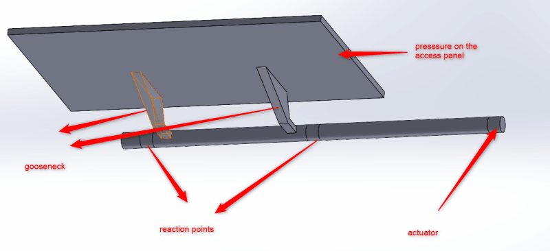
presumably you are looking at the shaft.

the door has two attmts (to the shaft). The applied load is presumably normal to the door. So at the shaft there will be a shear load (= applied) and a moment (which is torque on the shaft).
Now you can work out how the airload on the door distributes itself between the two attachments (or you can say equal loads, to get the solution going).

I would solve for torque first. There will be a load applied to the actuator arm (presumably), something maybe normal to the arm, or maybe acting along a defined line of action; but creating torque on the shaft. Now, this load may be determined by things like system pressure (so it may exceed the torque from the airload). This is ok; I suspect the shaft has a "stop" on it for just this condition, so it opens only so far. The stop will create the balancing torque. If this is a simple problem, then maybe you can put the actuator force is some convenient direction (like parallel with the airloads). Not the torque of the actuator is the same as the applied, but the force can be different if the torque arm is less.

Now you have all the loads applied so now you can solve for the reactions ... presumably the shaft is mounted into a couple of bearings (the "reaction points").
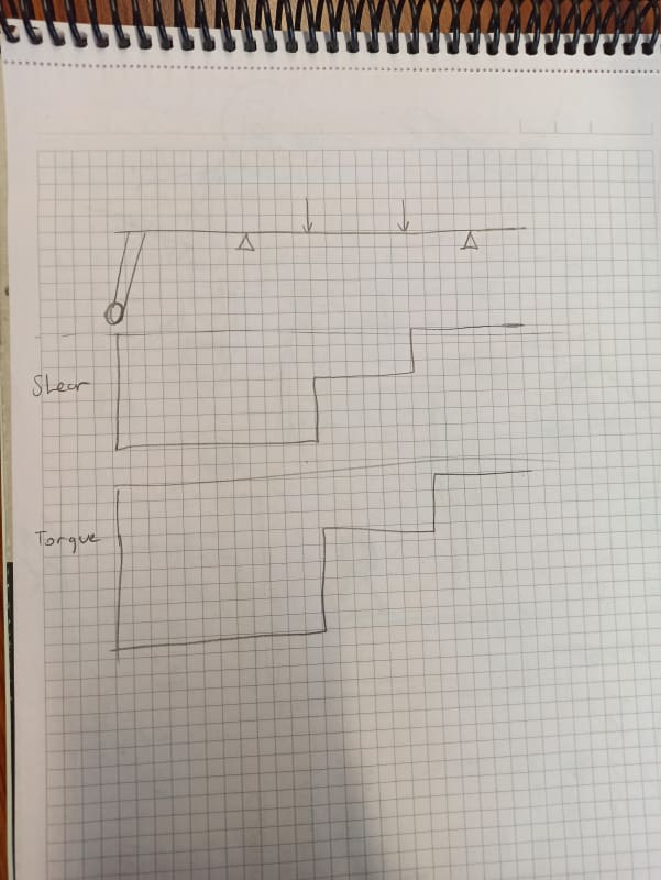
This needs equations of equilibrium, presumably in two directions (as I doubt all the forces are in the same direction. I'd start with the applied airloads as one direction ("x") and an orthogonal second direction "y". Maybe you can simplify the problem and say the actuator load is in the same direction (well, opposite) as the applied airload ... with all the forces in direction you can solve the actuator reactions more easily (sum Forces in one direction, sum moments about one point ... use one of the reaction points). Maybe in your case you can make the actuator arm the same as the airload arm, so the actuator force is equal to the airload. Note, this satisfies one equation of equilibrium, but there will still be reactions (they'll be a couple (so no nett force).

"Hoffen wir mal, dass alles gut geht !"
General Paulus, Nov 1942, outside Stalingrad after the launch of Operation Uranus.
 
Status
Not open for further replies.
Back
Top