Continue to Site

Eng-Tips is the largest engineering community on the Internet

Intelligent Work Forums for Engineering Professionals

  • Congratulations KootK on being selected by the Eng-Tips community for having the most helpful posts in the forums last week. Way to Go!

Help meshing a complex part: Part 2

Status
Not open for further replies.

ShadowWarrior

Civil/Environmental
Aug 21, 2006
171
In continuation of thread799-390004, I have the same geometry but with a vertical extension this time. I would appreciate community's help in achieving all Hexa mesh of this new part. The problem I'm facing is to partition it in appropriate regions to get all Hexa mesh.

This is the new part -
This is the mesh I got so far from the new part by following the previous partitioning scheme (green = structured = Hexa mesh). When trying to partition cell by defining cutting plane, the vertical part also get cut (see Red box). And its not possible to cut partition between the vertical part and the main cylinder (see black circle.
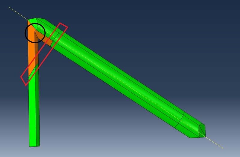
Untitled_dr8sis.jpg


PS: the previous problem was solved by simply deleting surfaces from unwanted regions in ABAQUS.
 
Replies continue below

Recommended for you

Try using edge loop cut.

Tsur G., Medinol.com
 
TsurG said:
Try using edge loop cut.
In ABAQUS part module? there seems to be no option in this name. Could you please guide me on how to do this?
 
Why not separate the two parts and mesh them separately, then tie the two parts together at the connecting surface. As it stands the combined part looks unsuitable for hex meshing due to the sharp angles at the intersection.

 
@corus - This is just a building block of a hierarchical structure, so there will be hundreds of tie required. Hex meshing the part as it is shown here will yield better result.
 
Does it need to be hex meshed? Could you use beams instead?
 
It must be all Hex meshed, beam will not do due to complex bending nature of the hierarchical structure formed by repeating pattern of the attached part.
 
@ShadowWarrior, you mentioned HUNDREDS of those?

If there is no complex contact, or unique non-linearity, the global solution will be better achieved by beams.
If you concern is with that corner, you can always remodel it using hexa and run a SubModel.

Tsur G., Medinol.com
 
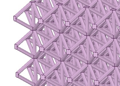
@TsurG, The resulting hierarchical structure will look like this -

Untitled_apmynv.jpg


The contact among the members are indeed complex (especially in the connection region), hence beams cannot be used. Different approaches have been tried in the previous thread, and meshing the repeating part in all Hex found to the best solution.
 
First, it would be easier to understand with a figure of a unit cell.

I'm still trying to understand your decision not to use beams. I couldn't find the thread you referred to.

As far as my understanding goes, the rods are not contacting in the joints - they are connected. Hence, no contact is introduced.
Else, there are huge deformations that deform the structure that much so rods will touch their neighbors.

Other approach might be using sub-structure.

Tsur G., Medinol.com
 
@TsurG, the structure will be subjected to impact loading, the members at the nodal regions do come into contact at 0.7 strain. Modeling with beam element has been tried but gave unreliable result.

I'll add a picture of unit cell when I come home later today, I appreciate everyone's response here in helping me.
 
OK,
Now I'm getting to understand the problem.

If it is a repeating cell structure, and you are interested in the whole structure response and not necessarily into the rods behavior,
you might want to consider using sub-structure in the form of Abaqus Substructure or defining unique material response in the element level.
Meaning, assuming the structure is homogeneous, you can replace each cell by element with matching behavior.
else, you can use the assumption of continuum mechanics and model it as a bulk.

T.

Tsur G., Medinol.com
 
TsurG said:
If it is a repeating cell structure, and you are interested in the whole structure response and not necessarily into the rods behavior,
you might want to consider using sub-structure in the form of Abaqus Substructure or defining unique material response in the element level.
Meaning, assuming the structure is homogeneous, you can replace each cell by element with matching behavior.
else, you can use the assumption of continuum mechanics and model it as a bulk.

This all can be avoided if this repeating part can be hex meshed, and usual FE approach could be followed in the analysis.
Is there anyway we can do the /CAE partitioning in another software and later import it?

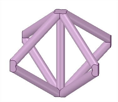
Below is the picture of the unit cell -

PrtScr_capture_ugghbi.jpg
 
I would really appreciate any help in this regard, my entire thesis is hanging on it.
 
I don't see how that part can be hex meshed in A/CAE.

The next best thing would be, that the connection area is meshed with tets and the straight region with hex. When you partition like that and assign these meshing techniques, then A/CAE should create the Tie constraint automatically.

If you are able to mesh that part in another tool, then you could import the mesh (.inp) and define everything else on the mesh in A/CAE.
 
Status
Not open for further replies.

Part and Inventory Search

Sponsor