Continue to Site

Eng-Tips is the largest engineering community on the Internet

Intelligent Work Forums for Engineering Professionals

  • Congratulations KootK on being selected by the Eng-Tips community for having the most helpful posts in the forums last week. Way to Go!

Help: Motor and Worm Gearbox Torque 1

Status
Not open for further replies.

Sirius2

Mechanical
Dec 15, 2002
67
Hello. I hope somebody will be able to help.

I have designed some equipment to assemble some large parts. It involves a stand and a fixture attached to it via a worm gear box.

The fixture and part needs to tip over at 90 degrees, from vertical to horizontal, and back.

After design and build, the specification has changed. I am not sure if the motor is going to be strong enough.


The total weight being lifted is 120kg.

The distance of mass from the pivot point is 280mm.

The current geared motor is 0.127 Nm. It is planetary geared to 100:1. Roughly I think this gives 12 Newton Meters.

The motor output Rpm is 60.

I have hooked this motor up to a 30:1 NMRV worm gear box, because 60rpm is too fast. I ideally wanted to rotate the fixture 90 degrees in less than 10 seconds, but no more than 20.


I have read that the calc for Final Torque is: Initial Motor Torque x Gear Ratio.

I have therefore taken the original motor torque and multiplied it by 130:1 total gearing. 0.127 x 130 = 16.5 Nm.


So far so good?.....


My weight is 120kg at 280mm from pivot. To get this back into meters, I have divided One Meter by 280mm, which gives 3.55. (Ie, 280mm fits 3.55 times into a meter).

120kg divided by 3.55 = approx 34kg at 1 meter. For certainty I am calling it 35kg.


So I have a mass of 35Kg at 1 meter from the pivot, which is then being worked back through a 30:1 worm gear box, then back to the 100:1 motor gearbox.

Is any of this right?


Can anybody help me understand what I now need to do with this 35kg, to know what the output torque of the motor needs to be, prior to the 30:1 gearbox?


Ie, taking the motor as it is now, at 12 Nm, or 16Nm through the second gearing, would this be enough to lift the weight?


Sorry if this is hard to understand, or something that is normally very simple for you guys. (Automation and motors etc are not usually my kind of work).

Many thanks

Sirius.
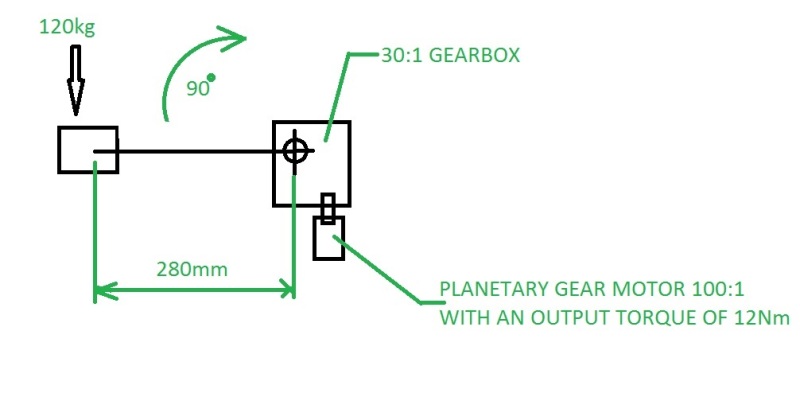
SKETCH_tv8stz.jpg
 
Replies continue below

Recommended for you

That sounds like a good idea. I will mention it tomorrow and, again, when the motor arrives on Monday.

I am in the process of re-designing the stand (to fit the new style of motor and to make the pillar rise and fall with the actuator), and I am going to make sure that the other motor could also be fitted into the space, to make sure it could be easily swapped later, if the need arose.

It seems the equipment ''is what it is'' now, and whatever we do to it in the future is going to cost....either rewiring to a new amp rate, or rewiring for a higher voltage altogether.

So, if all hell does break loose later down the line, at least we have a chance at obtaining a motor that can lift it, which fits into the design. We can test this one out, then, if it is no good, we can at least get the order started ready for the next two builds.

The shape and proportion of this fixture is such that most of the work is done vertically, then the dead-weight is moved from vertical, backwards, over the worm reducer box, until it becomes horizontal.

I think the initial lift will be the struggle, because all the weight is at one side of the pivot point. Seeing as the fixture (and part) is very tall, when the fixture gets to about 45 degrees, the weight of the fixture will start help lift it the rest of the way, as the weight starts to move over centre.

Moving it back down to vertical again is not so bad, because approx 40% of the fixture is still going to be hanging at the correct side of the pivot point to help it back down. Hopefully this will also help reduce the strain on the motor and the amps etc.


Cheers.
 
Yeah, the situation is not ideal Lukin1977.

I would prefer to wait for the right motor and make sure the cabling can handle the amps, but my hands are a bit tied on this now. The pressure is on to get it all finished and delivered. We couldn't wait up to 10 weeks for the other motor delivery. We will have to manage somehow, even if we have to resort to counterbalance weights.

There will be an operating manual supplied, in which we could highlight the limitations and issue some warnings. I know nobody tends to read them, but from my employers perspective (I suppose) they would kind of be 'covered' in an instance where it is clear the equipment has been abused.

The work cannot really be carried out on the job any quicker than the expected cycle time. If it was filling yoghurt pots, or powering a production line, I think there could be a risk of somebody new coming along and "cranking it up"..... but in our case, I don't tend to see it as being applicable. Sure, somebody may end up pushing for 6 parts an hour instead of 4, but it may not cause that much trouble to do so.

We could attach a badge saying no part over a certain weight is to be used on the equipment, etc, too, for what it would be worth.
 
My concern is someone raising the part and then immediately lowering it to check something. Then immediately raising it again. Several times.
"Look at how this works, Charlie."
"Hey that's neat. Show me again."
"OK"
"Wow. Nice, do it again."
"Hey Sam. Come and look at this go up and down."
Or something similar. Actions leading to failure may not always be reasonable, or logical.

Bill
--------------------
"Why not the best?"
Jimmy Carter
 
I've been gone doing real work.

If this is for an industrial environment or anything of the sort, why are you using 12 volts? Automotive motors for power windows and seats and windscreen wipers and the like are obviously 12 volts DC. But in my part of the world, anything industrial is either going to be 24 volts DC for low-powered equipment, or 120VAC single phase or 600VAC three phase.

There's no way I'd size something for an industrial environment close to "the edge". A motor that is perhaps a little bigger or stronger than it actually needs to be, you pay for once, and you never hear of it again. If it's only operating intermittently, make sure it can handle being operated continuously, but just beware that frequent starts and stops can be worse for a motor than just sitting there running steadily. If you slice the design and the motor sizing right down to the edge ... and you make a mistake ... and things don't quite work out as planned ... now you'll be doing it again, and this time it'll cost more.

The torque on your mechanism is pretty significant. It means your final stage reduction gearbox is going to have to be a decent sized unit to have the proper torque rating. Why try to operate this with a little microscopic motor that's just barely up to the task?

The power output that you are talking about for this application is somewhere near 70 watts. You need more because of friction, stiction, starting inertia, and the like, which everyone else has mentioned. That's into the region where AC motors start making sense. If you put a proper industrial (say) 1/2 horsepower AC motor on there with a proper gearbox from SEW Eurodrive or the like and which has the proper torque and speed ratings (and don't forget to pay attention to the overhung-load ratings on the shaft!!), it's gonna work, it's not gonna break, it's not gonna burn up, it doesn't matter how many times the operator hits the "start" button, and you'll never hear of it again. If you need variable speed then put a small VFD on the motor. Done. And if the end user somehow does manage to break it, they can get another one from the local Eurodrive distributor.

Yes, the initial price tag might be a bit more. Do it right ... or do it again.
 
I should add that many times back in my machine-design days, I talked my boss out of using cheap worm-drive gearboxes and substituted a good one from a reputable manufacturer instead. (We used SEW Eurodrive.) Not once did I ever regret doing so.
 
Thanks Brian.

In answer to your question about the 12volts.....it was just the way the job evolved. It started off being a very simple stand, with a tipping device (worm reducer)on the top to rotate an aluminium fixture plate at 90 degrees. The whole stand also had to rotate 180 degrees too, on a rotary base. The initial spec we were given was a maximum weight of 40 kilograms.

The idea behind the cheap worm box was that we'd just stick a crank handle on there and they'd tip it over by hand - with the option of adding some kind of motor (or air driven device, or even some kind of power-drill attachment) later. It was low volume work, so we did not see there being a problem with just winding it over with a handle. The motor was just a "what if" thing, which also sold the idea of using the reducer as a mechanism instead of gas struts, springs, counterweights, and so on (which would have been a nightmare, considering all the different weight parts being put on it).

This is how we set off. We designed and fabricated the stand first. It was all done, finished and powder coated. In the meantime, the customer had more meetings and decided they couldn't live with a handle on it, as the workers may complain due to the frequency of use they now had planned. It had to be driven. Oh, and the stand now had to be able to rise and fall too....!

So, not knowing anything about motors, or AC or DC or amps, I was tasked with finding something cheap-ish to remove the handle, and something to power the stand up and down. (Bear in mind that the original max weight was going to be 40kg).

Mistakenly, as I now know, I made a rough calculation at what I thought would handle 40kg and a factor of safety....so I was looking at the the stated "Torque Output" on the motor as being 11.9 Nm, and thought this would do it. I now know this is the "stall torque" and not the actual "output torque" for normal working of the motor. The linear actuator, from the same supplier, was 12 volts and could handle 400kg.

The customer then said they hadn't the budget for that yet - and could we send them the 'fixed height' tower, with the motorised tilting top on. It needed foot pedal controls, relays, limit switches - and they decided they only wanted the top to tilt when the stand was turned away from the operator. So, we bought the motor, got somebody to get the electrics for the control box, added microswitches, safety stop button, and so on.

So there it was, a tower that went 180 degrees and back on the base, with a motorised tilting top, and we attached some 50kg weights to the top and powered it back and forward quite easily. Great, we thought. All that would be needed next, when the next quarters budget clears, is the 12v actuator and a modification to the stand to make it go up and down.

In the meantime......we start investigating the fixture requirements. It developed from what we were initially shown, into something that, itself, weighed over 50kg without even a part being in it! No longer was it a simple plate, but a much more complicated and larger thing. I whittled the weight down as much as possible to around 40kg. But we knew the stand would only lift this, not much else.

So here we are, £1000 or so for the control box, then a motor, worm drive reducer, all at 12 volts. Let alone all the design hours and manufacture based on those things. The customer offers to pay for something to beef up the motor.....but we are told our whole electric control box would be scrapped if we change the voltage. We say we may have to factor in that loss and g to 24 volts.

In the meantime, I try and learn how to properly work out the torque for the new maximum weight - which is now 120kg and not 40kg. I was not too sure I had it right, but I was coming out with about 12Nm. Looking at 24volt gearmotors, the torque was only ever a fraction more than the 12 volt ones. It was overall so slight that it hardly made sense scrapping off the £1000 control box and equipment.

I thought we may have to go to industrial motors, three phase or single phase, 230 volts. However, we were told from the electrician we hire that 230 volts on this equipment would be dangerous, we were better at 12 or 24, preferably 24, and that it would cost a lot of money, the motor may be hard to reverse, and the because the power cables go up through the middle of the stand, twisting 180 degrees and back, it would be a hazard if that cable eventually broke inside the stand. We asked about some kind of rotary connector to power that kind of voltage, and he said they'd be far too expensive. Also, that splitting the cabling off to run a 24v actuator at the same time as a 230v motor would add extra issues.

So, I started searching again for 12 volt motors. Bigger ones. Putting in the specification values of "speed" "voltage" "output torque".....

I found some that had an output of 25Nm! Wahey!! I only needed about 12! So I thought we were going to cream it, save the equipment, save the design, and continue with the 12 volt actuator too - which we could have added to the existing control box with little work.

I wanted to make sure I was not working things out wrong though, so I thought I'd ask online about the torque. Again, it was found to be 11Nm or so......and you know the rest.

So, that's the tale.....and indeed, it is a lesson learnt in more than one ways. 1) Ensure we nail down all the specifications first! 2) Go for a more than adequate motor based on those specs! or may be 3) Steer well clear of anything that adds motors and electrics to our normal work!

Cheers.
 
Any chance for a counterweight to balance the weight of the fixture and part of the item?

One can drop a lot of torque that way.
 
I had that once. Our original estimate for parts to build some training equipment was $800.
Fortunately for me, every step in the escalation was priced and approved.
In the end we spent $20,000 on parts and were congratulated on a job well done.
That has happened once in my lifetime and I don't expect it will ever happen again.

Bill
--------------------
"Why not the best?"
Jimmy Carter
 
Its hard to me to accept that you MUST use 12V because of a potencial cable breakage. I mean, there must be another "solution"
 
Status
Not open for further replies.

Part and Inventory Search

Sponsor